J
James JoyceAug 6, 2025
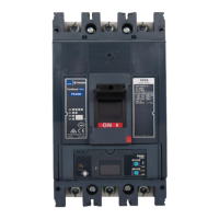
Why is my NHP Circuit breaker nuisance tripping?
- RRobert RobinsonAug 6, 2025
Nuisance tripping in NHP Circuit breakers can occur even when the rated current hasn't been reached due to several factors: * **Vibration and/or shock:** Dampen the vibration of the MCCB and review installation requirements. * **High proportion of high-frequency distortion in load current:** Decrease the distortion content of the load circuit. * **Electromagnetic induced interference:** Review nearby sources of conducted and radiated emissions. * **Excessive surge:** Isolate and mitigate the surge source. * **Erroneous connection of control circuit for SHT or UVT:** Verify the control wiring and supply to the SHT and UVT.