1-2 | ni.com
Chapter 1 Getting Started with the cDAQ Chassis
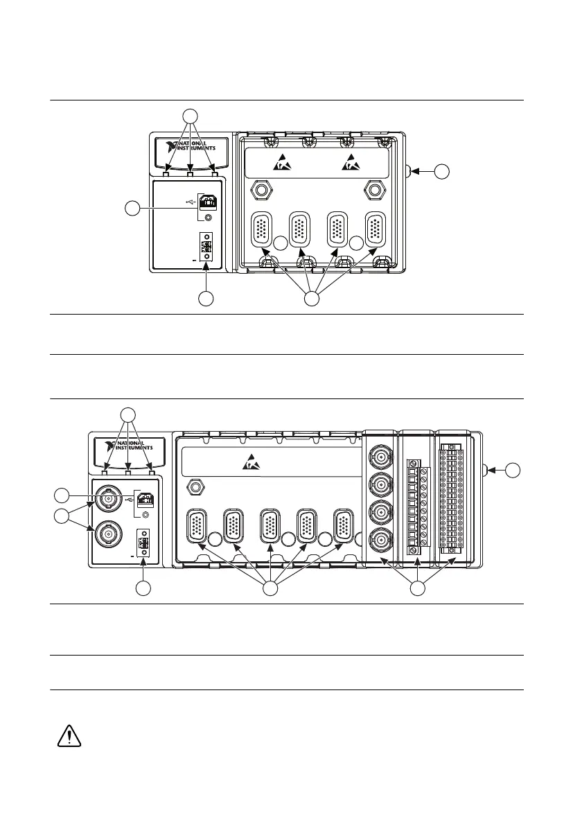
Figure 1-2 shows the NI cDAQ-9174 chassis.
Figure 1-2. NI cDAQ-9174 Chassis
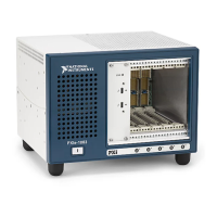
Figure 1-3 shows the NI cDAQ-9178 chassis.
Figure 1-3. NI cDAQ-9178 Chassis
Safety Guidelines
Operate the NI cDAQ-917x chassis only as described in this user manual.
Caution Refer to the Read Me First: Safety and Electromagnetic Compatibility
document for important safety and electromagnetic compatibility information. To
1 POWER, READY, and ACTIVE Status LEDs
2 USB Connector with Strain Relief
3 9–30 VDC Power Connector
4 Module Slots
5 Chassis Grounding Screw
1 POWER, READY, and ACTIVE Status LEDs
2 USB Connector with Strain Relief
3 TRIG 0 (PFI 0) and TRIG 1 (PFI 1) BNC Connectors
4 9–30 VDC Power Connector
5 Module Slots
6 Installed C Series Modules
7 Chassis Grounding Screw
4321
INPUT
9-30 V
15 W MAX
POWER READY ACTIVE
V
C
NI cDAQ-9174
NI CompactDAQ
3
4
5
1
2
123 45
INPUT
9-30 V
15 W MAX
POWER READY ACTIVE
V
C
NI cDAQ-9178
NI CompactDAQ
TRIG 0
TRIG 1
3
4
5
6
7
1
2