© National Instruments | 1-11
NI cDAQ-917x User Manual
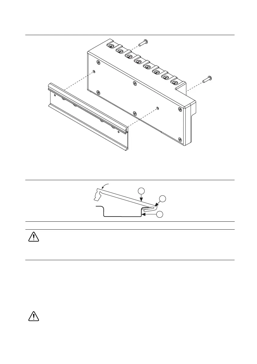
Figure 1-8. NI cDAQ-9174/9178 DIN Rail Installation
Clip the chassis onto the DIN rail with the larger lip of the DIN clip positioned up, as shown in
Figure 1-9.
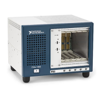
Figure 1-9. DIN Rail Clip Parts Locator Diagram
Caution Remove the I/O modules before removing the chassis from the DIN rail.
NI cDAQ Chassis Features
The cDAQ chassis features a chassis grounding screw, USB cable strain relief, and LEDs.
Multislot cDAQ chassis have a power connector and the NI cDAQ-9178 chassis also features
two TRIG (PFI) BNC connectors. Refer to Figure 1-1, 1-2, or 1-3 for locations of the cDAQ
chassis features.
Chassis Grounding Screw
Caution To ensure the specified EMC performance, the cDAQ chassis must be
connected to the grounding electrode system of your facility using the chassis ground
terminal.
1 DIN Rail Clip 2 DIN Rail Spring 3 DIN Rail
1
2
3