1-12 | ni.com
Chapter 1 Getting Started with the cDAQ Chassis
The wire should be 1.31 mm
2
(16 AWG) or larger solid copper wire with a maximum length of
1.5 m (5 ft). Attach the wire to the earth ground of the facility’s power system. For more
information about earth ground connections, refer to the KnowledgeBase document, Grounding
for Test and Measurement Devices, by going to
ni.com/info and entering the Info Code
emcground.
Note If you use shielded cabling to connect to a C Series I/O module with a plastic
connector, you must attach the cable shield to the chassis grounding terminal using
1.31 mm
2
(16 AWG) or larger wire. Use shorter wire for better EMC performance.
USB Cable Strain Relief
You can provide strain relief for the USB cable by using the jackscrew on a locking USB cable
to securely attach the cable to the chassis.
LEDs
The cDAQ chassis features two status LEDs: ACTIVE and READY. The ACTIVE LED
indicates cDAQ chassis USB bus communication. The READY LED lights when the cDAQ
chassis is ready for use.
NI cDAQ-9174/9178 chassis also features a POWER status LED.
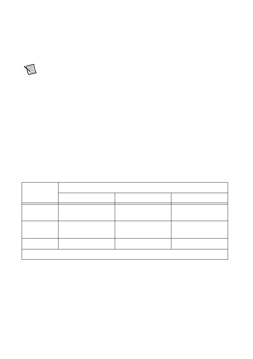
Table 1-2. LED State/Chassis Status
Status LED
LED Color
Off Green Amber
ACTIVE No USB traffic
present/suspend
USB traffic present Unconfigured
READY USB connection is not
established/suspend
Full-Speed (12 Mb/s) Hi-Speed (480 Mb/s)
POWER
*
No power supplied Power supplied —
* NI cDAQ-9174/9178 chassis only.
 Loading...