Emptying the brine system
In order to service the brine system it may be easier to
drain the system first. This can be done in different ways
depending on what needs doing:
Draining the brine system in the cooling module
If, for example, the brine pump requires replacing or the
cooling module requires servicing, drain the brine system
by:
1.
Close the shut-off valves to brine system (QM33) and
(QM34).
2.
Connect a hose to the drain valve (QM2), place the
other opening of the hose in a container and open
the valve. A small amount of brine will flow into the
container.
3.
Air must get into the system in order for the remain-
ing brine to run out. To let in air, slacken off the
connection slightly at the shut-off valve (QM33) that
joins the heat pump with the cooling module.
When the brine system is empty, the required service
can be carried out.
Draining the brine system in the heat pump
If the heat pump requires servicing, drain the brine sys-
tem by:
1.
Close the shut-off valve outside the heat pump for
the brine system.
2.
Connect a hose to the drain valve (QM2), place the
other opening of the hose in a container and open
the valve. A small amount of brine will flow into the
container.
3.
Air must get into the system for the remaining brine
to run out. To let in air, slacken off the connection
slightly at the shut-off valve that joins the brine side
with the heat pump at connection (XL7).
When the brine system is empty, the required service
can be carried out.
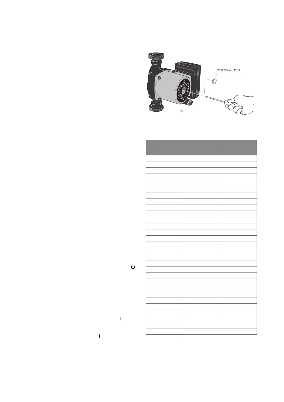
Helping the circulation pump to start
1.
Shut off, F1155 by setting the switch ((SF1)) to " ".
2.
Remove the front cover
3.
Remove the cover for the cooling module.
4.
Loosen the venting screw (QM5) with a screwdriver.
Hold a cloth around the screwdriver blade as a small
amount of water may run out.
5.
Insert a screwdriver and turn the pump motor
around.
6.
Screw in the venting screw (QM5).
7.
Start F1155 by setting the switch (SF1) to "" and
check whether the circulation pump works.
It is usually easier to start the circulation pump with
F1155 running, switch (SF1) set to " ". If the circulation
pump is helped to start while F1155 is running, be pre-
pared for the screwdriver to jerk when the pump starts.
The image shows an example of what a circulation pump can look
like.
Temperature sensor data
Voltage (VDC)Resistance
(kOhm)
Temperature
(°C)
3.256351.0-40
3.240251.6-35
3.218182.5-30
3.189133.8-25
3.15099.22-20
3.10574.32-15
3.04756.20-10
2.97642.89-5
2.88933.020
2.78925.615
2.67320.0210
2.54115.7715
2.39912.5120
2.24510.0025
2.0838.04530
1.9166.51435
1.7525.30640
1.5874.34845
1.4263.58350
1.2782.96855
1.1362.46760
1.0072.06865
0.8911.73970
0.7851.46975
0.6911.24680
0.6071.06185
0.5330.90890
0.4690.77995
0.4140.672100
55Chapter 9 | ServiceNIBE F1155

 Loading...


