F1345/F1355
F1345 without 2.0
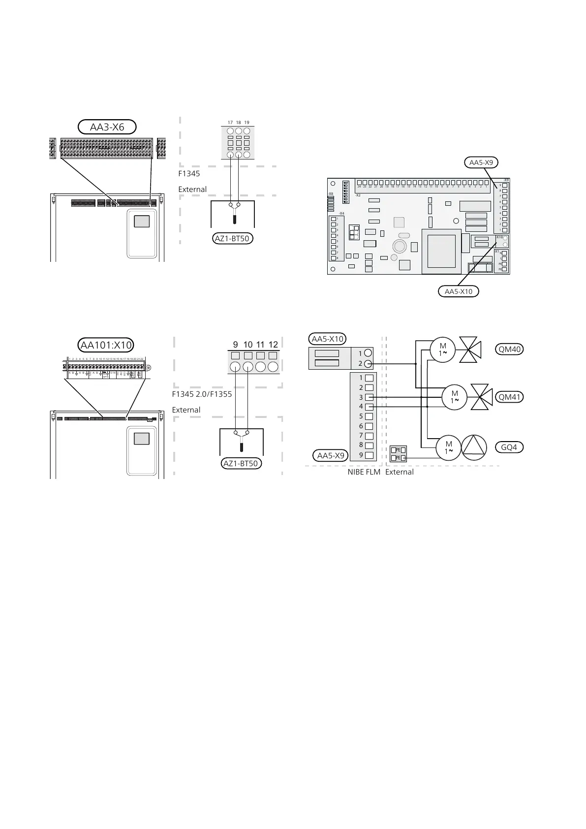
Room sensor (AZ1-BT50) is connected to any AUX input
(AA3-X6:17-19)
F1345 with 2.0/F1355
Room sensor (AZ1-BT50) is connected to any AUX input
(AA101-X10:9-14, 19-22)
F1345 2.0/F1355
External
AZ1-BT50
L1
-X3
-X4
1 2
3
-AA101 -AA101
N
L2
L3
1 2
3
4
5
6
7
8
9
-X5
1 2
3
4
5
6
7
8
9
-X6
-X7
-X8 -X9
-FC1
-AA101 -AA101
-AA101 -AA101 -AA101
1 2
3
4
1 2
3
1 2
3
1 2
3
4
5
-X10
A B A B
-AA3-X7
K1
-AA101
K2
K3
C C
NO
NC
K4
C
NO
NC
QN10 GP16
L N L L L N N N L N L N
PE
PE
6
7
8
9 10
1112
13
14
15
16
17
18
1920
2122
12V
A B
13
14
-BE1
-GP16
-BE2
-BE3
AUX 4
AUX 5
1 2
3
4
5
6
7
8
9 10
1112
13
14
15
-AA3
-X6
0-10V
-EP14
-EP15
-BF1
16
17
18
2
-AA3
-X22
-AA3
-AA3
-X20
-X21
1
3
12
3
-X23
-BT1
-BT50
-BT25
-BT6
AUX 1
AUX 2
AUX 3
-BT7
-BT71
2.0
1 2
3
4
5
-X10
A B A B
-AA101
6
7
8
9 10
11 12
13
14
15
16
17
18
19 20
21 22
12V
A B
13
14
-BE1
-GP16
-BE2
-BE3
AUX 4
AUX 5
0-10V
Connection of duct fan and damper for FLM
cooling
Connect the fan (GQ4) and the damper (QM40) (QM41)
for AA5-X9:4 (signal), AA5-X9:3 (N) and AA5-X10:2
(230V).
The connection on AA5-X10 and PE are occupied and
these must be spliced with a clamp.
ON
1 2 3 4 5 6 7 8
-X9
-X2
24 20212223 1516171819 1011121314 56789 1
1
N
L
PE
PE
1
2
3
4
5
6
7
8
2
3
4
5
6
7
8
9
234
-X8
-X4
-X10
-X1
AA5-X10
AA5-X9
ExternalNIBE FLM
GQ4
QM41
QM40
21Chapter 5 | Electrical connectionsNIBE FLM

 Loading...


