CONNECTING TO ANOTHER HEAT PUMP
In cases where NIBE FLM is installed together with an-
other heat pump, connect the exhaust air module to a
grounded single phase wall socket or through a perman-
ent installation. For permanent installations, NIBE FLM
must be preceded by a circuit breaker with at least a 3
mm breaking gap.
For installation with another heat pump, do not connect
control cable (W6).
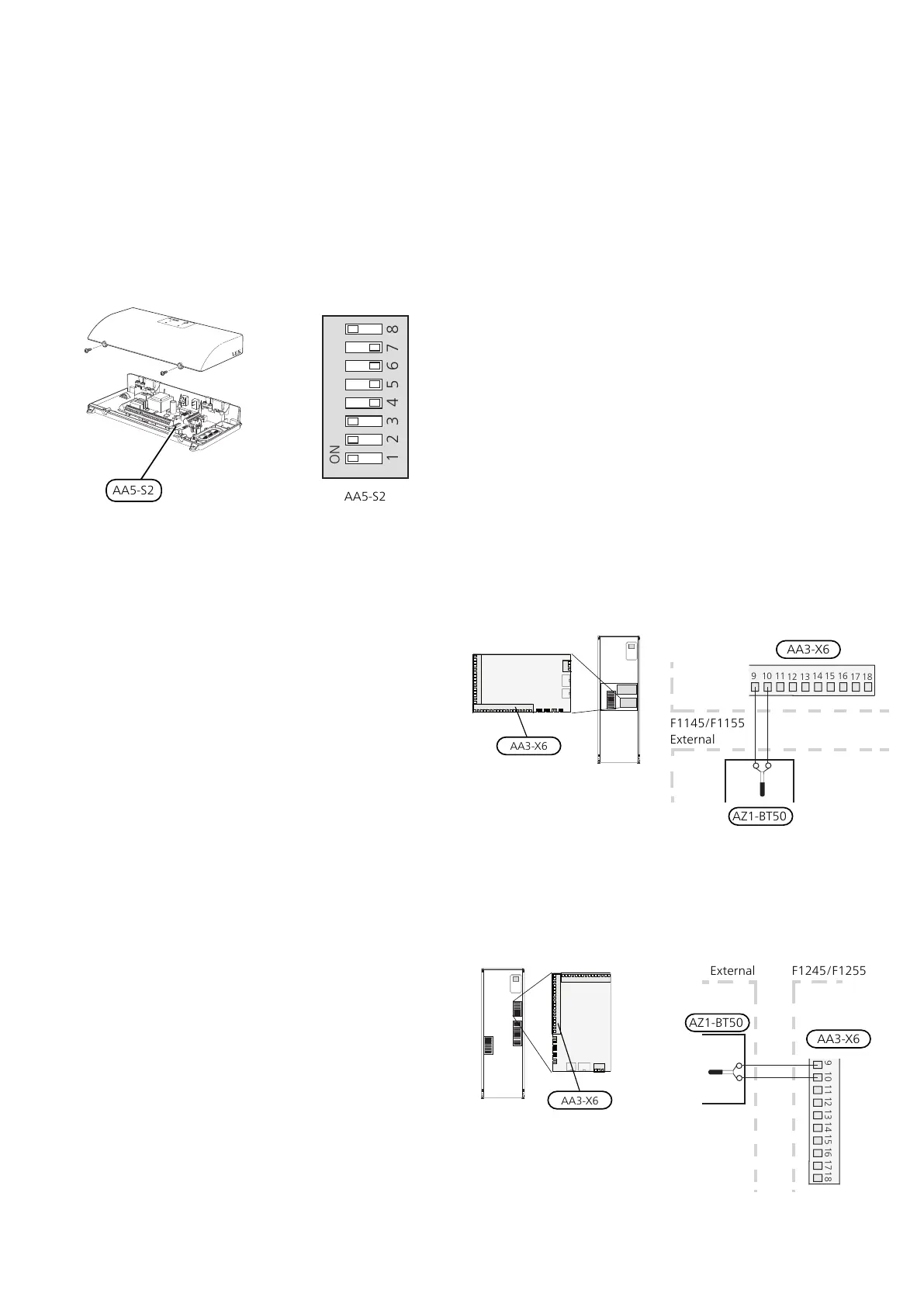
The DIP switch (AA5-S2) must be set as follows.
OPTIONAL CONNECTIONS
Room sensor for FLM cooling
For optimum function, a separate room sensor (AZ1-
BT50) should be connected when installing with cooling.
This sensor is placed in the room that is to be kept
coolest. The room sensor has up to three functions:
• Offers the opportunity to set a different target temper-
ature in the room that is to be kept coolest.
• Show current room temperature in the display on the
heat pump.
• Provides the opportunity to activate FLM cooling.
Install the sensor in a neutral position where the set
temperature is required, 1.5 m above the floor. It is im-
portant that the sensor is not prevented from measuring
the correct room temperature, for example by being
located in a recess, between shelves, behind a curtain,
above or close to a heat source, in a draught from an
external door or in direct sunlight. Closed radiator ther-
mostats can also cause problems.
Connection of room sensor for FLM cooling
F1145/F1155
Room sensor (AZ1-BT50) is connected to any AUX input
(AA3-X6:9-18).
AA3-X6
External
F1145/F1155
AZ1-BT50
F1245/F1255
Room sensor (AZ1-BT50) is connected to any AUX input
(AA3-X6:9-18).
AA3-X6
External
AZ1-BT50
F1245/F1255
NIBE FLMChapter 5 | Electrical connections20

 Loading...


