10
6 - WIRING AND CONNECTIONS
Table 1 - MAXIMUM RUN (FT) PER WIRE GAUGE
110V AWG 14 12 10 8 6 4
MAX RUN (ft) 180 280 460 700 1150 1800
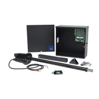
120VAC Input connection
ISOLATE ALL ELECTRICITY PRIOR TO INSTALLATION OR SERVICE
• Disconnect power to the gate operator by manually opening its dedicated
circuit breaker before making any mechanical or electrical adjustments.
• Use a 20 Amp dedicated circuit breaker for each installed gate operator.
• Open dedicated circuit breaker supplying power to this gate operator
BEFORE a new installation or making any modications to an existing
installation of this gate operator.
• All wiring connections MUST be made by a qualied individual.
• Run individual circuits in separate U.L. listed conduits. Do not combine
high voltage (120VAC) power wiring and low voltage (+12VDC to +24VDC)
control wiring in the same conduits.
• Use the information in table 1 to determine high voltage wire size
requirements. The distance shown in the chart is measured in feet from the
operator to the power source. If power wiring is greater than the maximum
distance shown, it is recommended that a service feeder be installed. When
large gauge wire is used, a separate junction box must be installed for the
operator connection. The wire table is based on stranded copper wire. Wire
run calculations are based on a 110 VAC power source with a 3% voltage
drop on the power line, plus an additional 10% reduction in distance to
allow for other losses in the system.
This gate operator system should be grounded through the earth ground in the
AC mains wiring system (GREEN WIRE).
PROPER EARTH GROUND CONNECTION REQUIRED FOR ALL
INSTALLATIONS!
Use the connection shown for connecting 120VAC power to this system.
WARNING: External entrapment protection must be added to insure a
safe vehicular gate operating system.
This swing gate operator uses an inherent entrapment sensing system as well
as external type sensors.
Entrapment protection must be provided by a combination of non contact
inherent devices. Disconnect power to the gate operator before installing the
non contact sensors.
Actual placement of sensors is dependent on the specic installation
requirements.
One or more non contact sensors should be located where the risk of
entrapment or obstruction exists such as the perimeter reachable by a moving
gate or barrier.
Use only U.L. listed (or equivalent) non contact sensors. Inputs from the photo
beam to the circuit board are Normally Open (N.O.). Use only U.L. listed (or
equivalent) non contact sensors.
Connect the non contact sensors. Inputs from the photo beam to the circuit
board are Normally Open (N.O.). Photo beam input shall REVERSE travel of
gate when activated during the CLOSE CYCLE ONLY. Gate will resume normal
operation when photo-beam is no longer activated. To reduce the risk of
SEVERE INJURY or DEATH:
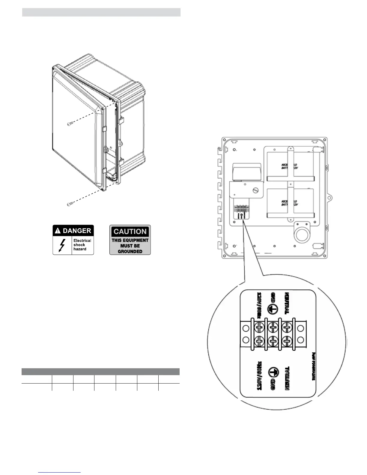
Remove the screws from the cover and open the door. Place the screws in
a safe location until the installation is complete. Once complete, replace the
screws in the cover door.
NOTE: These screws must be replaced to ensure security for the
system and to ensure an adequate seal of the cover.