12
SAVE COVER AND SCREWS !
Don’t over tighten the lock nut to the attachment bolt
F = 1 3/4”
7.3 - Removing the top cover
Locate the top cover and remove the two screws.
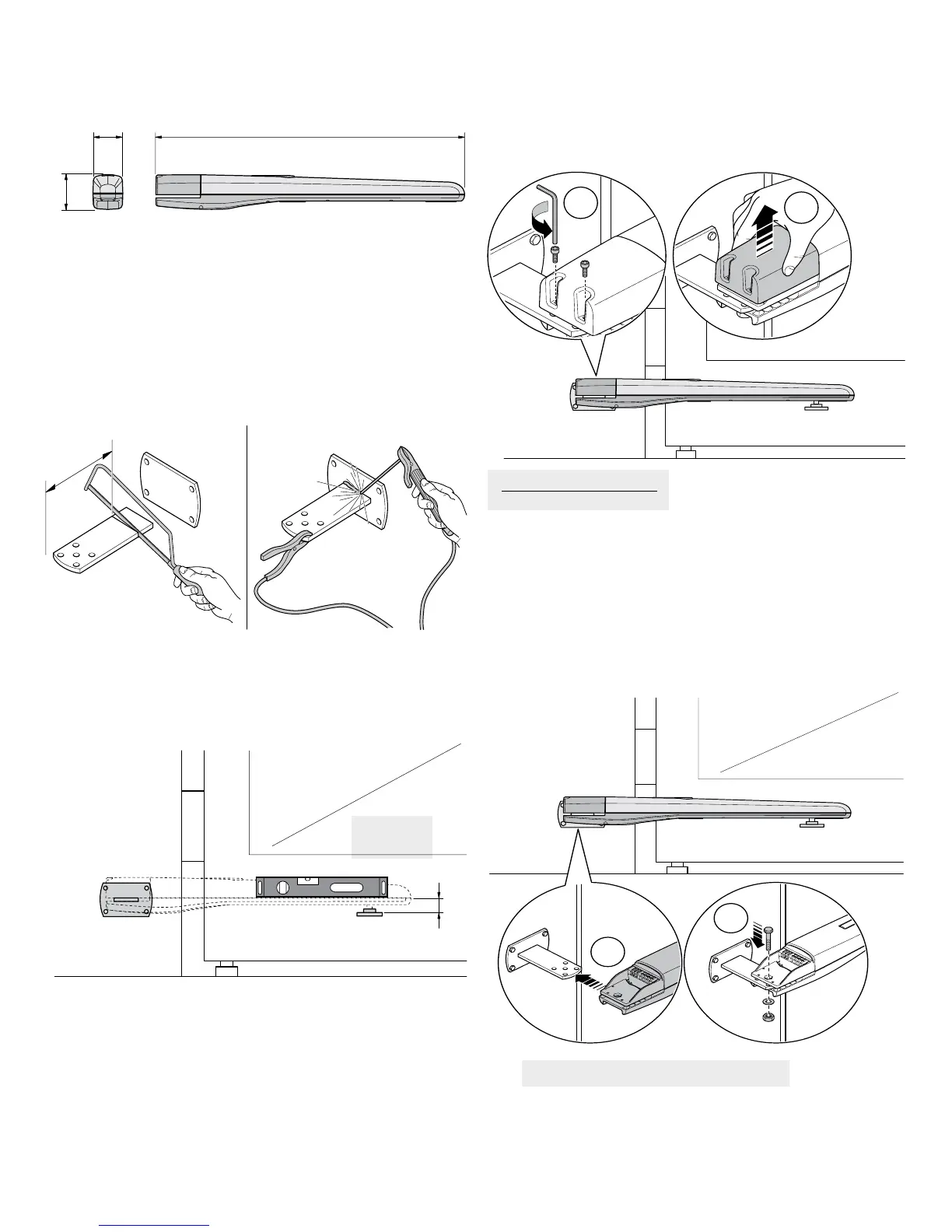
T5 DIMENSIONS
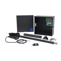
7.2 - Pivot and gate bracket attachment
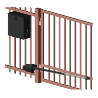
Cut the pivot bracket and weld being careful to check that the bracket is
level, using the base plate if necessary.
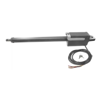
7.4 - Attaching the actuator
Slide the back end of the gate operator onto the pivot bracket. Insert the
bolt, washer, and locknut as shown in the diagram. Be careful to not to
over-tighten the locknut. The bolt should be sufciently tightened to securely
fasten the gate operator to the pivot bracket.
Attach the gate attachment bracket to the gate based on the position and
dimension shown. The actuator must be fastened to the gate in a completely
level position. Ensure that the gate attachment bracket is located at a “hard
point” on the gate suitable for opening or closing the gate.
ATTACHMENT BRACKET LOCATION
38”4 ½”
4 ¹⁄
8
”
T5 Actuator Dimensions