19
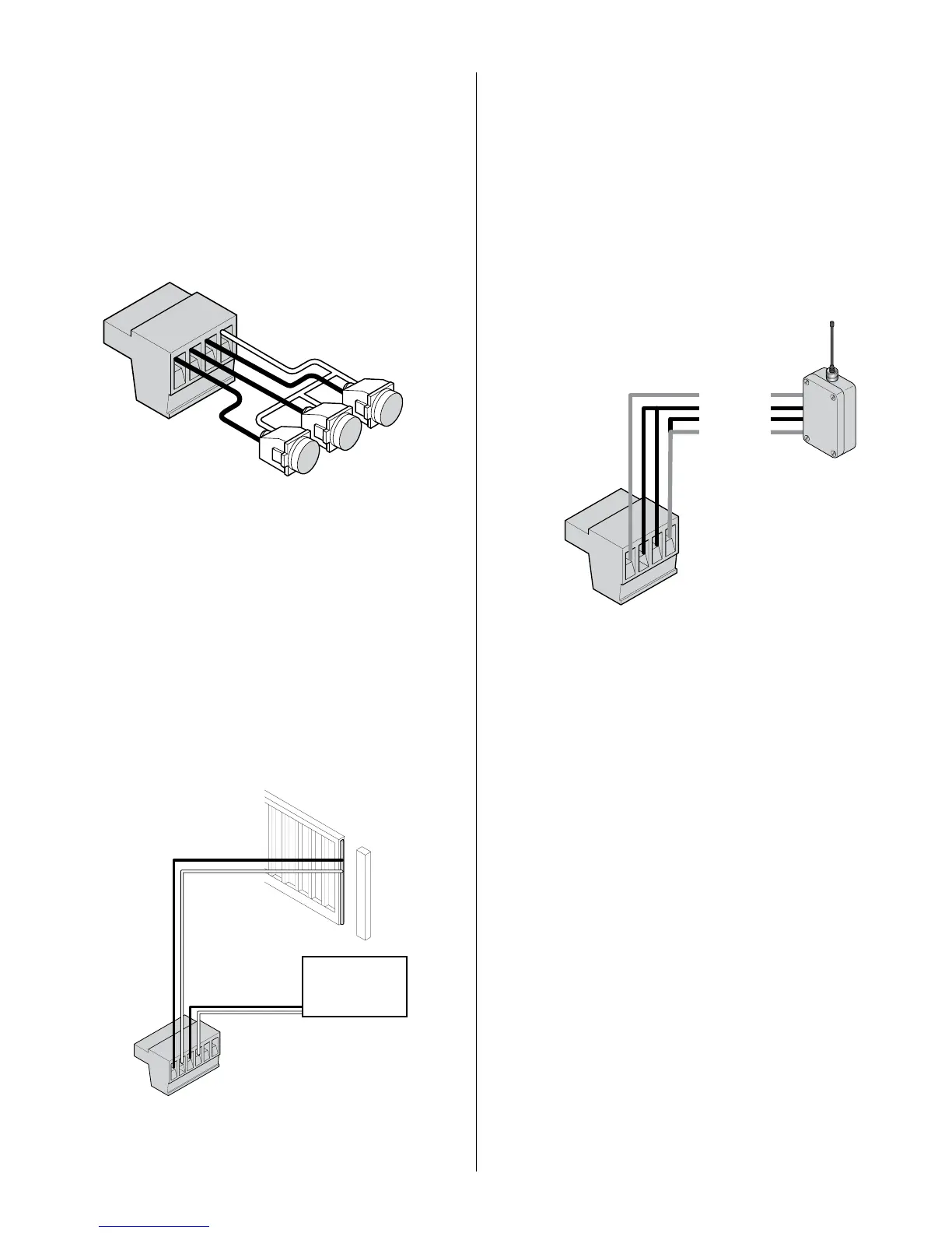
11.3 - Guard station
34 OPEN
35 STOP
36 CLOSE
37 GND
With the Guard Station switches installed, the user can operate the gate by
pushing the respective buttons for the command that is desired. Gate Open,
Stop, and Close dry contact inputs, are controlled by NORMALLY OPEN
(NO) and NORMALLY CLOSED (NC) momentary switches.
NOTE: If the guard station inputs are not used
STOP (35) and GND (37)
need to be tied together
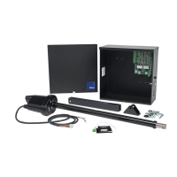
11.5 - Radio receiver connection (third party)
38 12V
39 OPEN
40 CLOSE
41 GND
The customer supplied radio receiver allows the gate operator to be operated
via remote, such as wireless keycard readers or user remote controls.
Connecting the Open (39) and Close (40) pins together with a receiver
enables single button gate control. This conguration allows a single button
to control the gate in the following sequence:
Press - Gate Open
Press - Gate Stop
Press - Gate Close
Press - Gate Stop
11.4 - Exit and edge inputs wiring diagram
28 EDGE
29 GND
30 EXIT
31 GND
The EDGE input may be congured as a monitored ANALOG input, or
DIGITAL (NC or NO) input. The EDGE sensor input is intended for ANSI/UL
325 listed gate edge sensors to protect against entrapment and hazardous
pinch points along the moving edge of the closing gate. The EXIT sensor
input is provided to activate to open the gate, or reopen a closing gate, upon
sensing an exiting vehicle.
34
35
36
37
CLOSE
STOP
OPEN
NO
NC
28
29
30
31
32
33
Exit Device
38
39
40
41
12V Power
Normally Open
Common
Ground