14
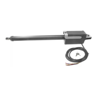
Connect motor power and control wiring as shown for motor 1.
Motor 2 connections identical for dual leaf gate.
MOTOR CONNECTION AT THE CONTROL BOARD
Motor 1 Motor 2
7.8 - Learning and programming features
The learning procedure consists of the following steps shown below:
1. Install electrical power to the control box.
2. Install all gate accessories such as Photo Eye’s, Sensors, Loops and
other safety devices.
3. Turn on the electrical power to the unit.
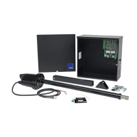
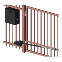
4. Using the MANUAL RELEASE, disengage the drive motor if this is not
already accomplished as shown.
7. Adjust the Mechanical Stop against the pin for the gate bracket.
5. Move the gate manually (with your hands) to ensure that the gate travels
to the fully open and fully closed positions with no binding or problems.
Gate should move freely. Push the gate to the CLOSED position. The
control board is already in the “LEARNING MODE” when shipped. If
not in learning mode press FUNCTION then press LEARN then press
SWING then SELECT LIGHT, AVERAGE OR HEAVY, then press ENTER.
6. Manually move the gate midway and engage mechanical release and
stow handle. Test motor direction by pressing OPEN. If the gate instead
CLOSES swap the RED and BLACK motor leads. Using the OPEN
button on the front of the Control board, hold the button down until the
gate reaches the fully intended open position.
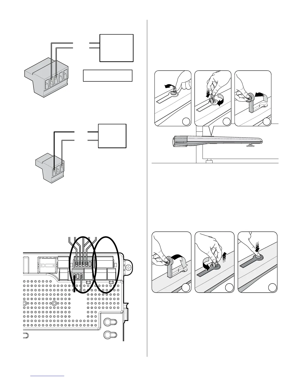
7.6 - Actuator limit switch and motor wiring connection to
the control board
T524V
Actuator
T524V
Motor
leads
Yellow: Motor encoder signal
Blue: Common
yellow
blue
red
black
Connect the Apollo T524V actuator motor leads to the 3-pin connector
as shown. Note: If the gate moves in the opposite direction from what is
expected, reverse the actuator wiring from what is shown. (Red to Pin 3,
Black to Pin 1).
Note - If gate moves in opposite direction from what is expected, reverse the
motor power lead wiring. (Red to pin 3, Black to pin 1)