15
8. Using the CLOSE button on the front of the Control Board, hold the
button down until the gate reaches the fully intended closed position.
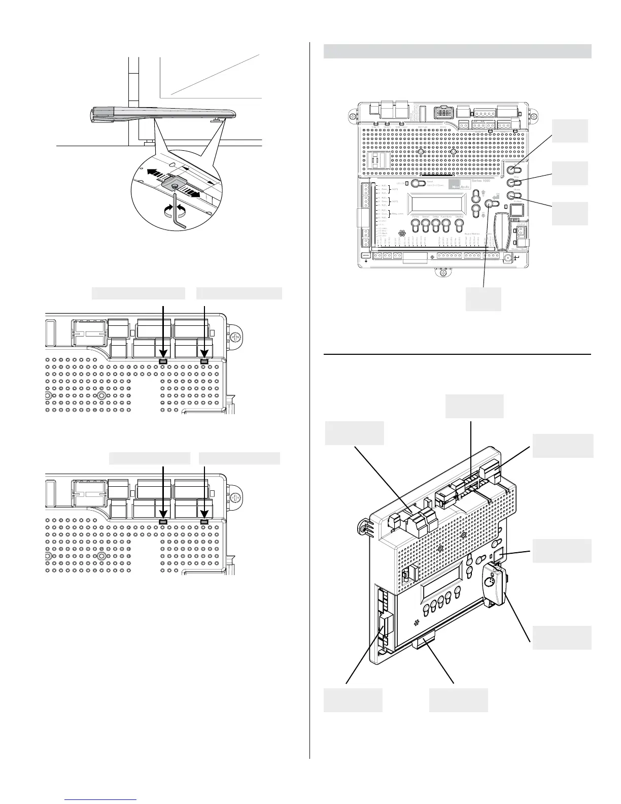
9. Adjust the Mechanical Stop against the pin for the gate bracket.
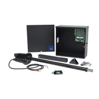
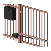
MOTOR 2 LED - REDMOTOR 1 LED - RED
MOTOR 2 LED - GREEN
Green OPEN LED
Red CLOSE LED
10. Press “OK” to allow the control board to scan for attached items, such as
sensors, photo eye’s and other safety devices.
11. The gate will open partially then stop. This is being done, so that the
control board can sense the type and operational condition of the drive
motor. The gate will then run to the closing limit (one leaf at a time in case
of dual application:“slave” closes rst then “master” follows), so that the
control board can properly sense the close limit trigger.
10. The control board will then OPEN the gate slowly to establish travel and
limits by sensing the open limit trigger.
13. Once the gate reaches the fully OPENED limit switch, the control board
will now increase gate travel speed to the highest speed allotted, and will
now travel to the fully CLOSED position at full speed.
14. The gate opener is now programmed for basic usage.
8 - CIRCUIT BOARD LAYOUT
ENTER
OPEN
STOP
CLOSE
INPUTS
POWER
INPUTS
MOTOR 1
CONNECTION
MOTOR 2
CONNECTION
PLUG IN
RECEIVER
COMM BUS
OUTPUTS
CONTROL BOARD BUTTONS
CIRCUIT BOARD LAYOUT
MOTOR 1 LED - GREEN