EasyManuals Logo

Nice Wingo User Manual

Nice Wingo
57 pages
To Next Page IconTo Next Page
To Previous Page IconTo Previous Page
Page #41 background imageLoading...
Page #41 background image
37
E
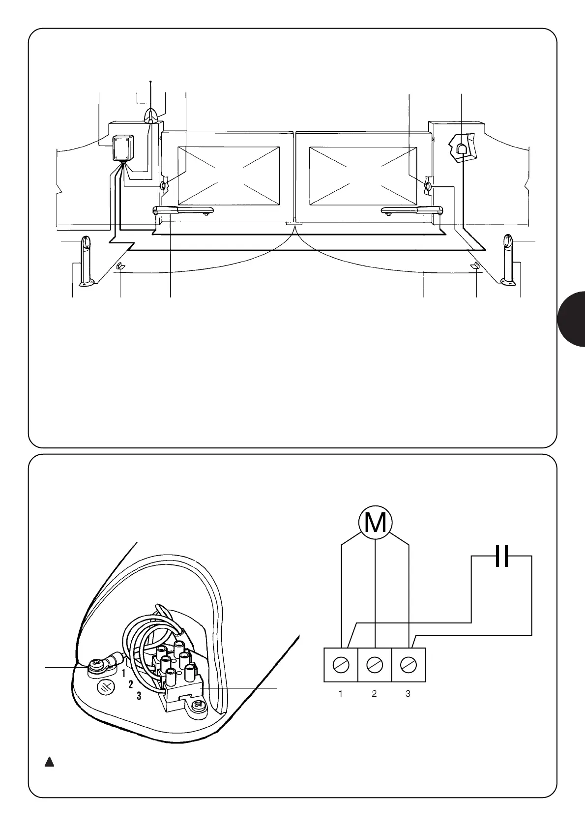
2.4) Instalación típica
7
7
3
1
2
8
7
6
5
4
7
1
2
8
9
1 Columnas para fotocélulas
2 Par de topes de apertura
3 Línea eléctrica de alimentación
4 Central de mando A400
5 Antena
6 Luz intermitente
7 Fotocélula
8 Actuador WINGO
9 Selector de llave o teclado digital
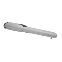
2.5) Conexión al motorreductor
Respetando la numeración de la tabla, realice las conexiones a la
regleta de bornes (A), siguiendo el esquema eléctrico.
A
NEGRO
ABRIR COMÚN CERRAR
5uF
AZUL VERDE
BLANCO
BLANCO
B
Recuerde de connectar siempre el cable de tierra (B)
como previsto por las normativas vigents (EN 60204 - CEI
64-1, EN 60335)
!

Table of Contents

Questions and Answers:

Question and Answer IconNeed help?

Do you have a question about the Nice Wingo and is the answer not in the manual?

Nice Wingo Specifications

General IconGeneral
Protection LevelIP44
Protection RatingIP44
Power Supply230V AC
Operating Voltage230 V
Opening Speed15s
Closing Speed15s
Safety FeaturesObstacle detection

Related product manuals