45
PL
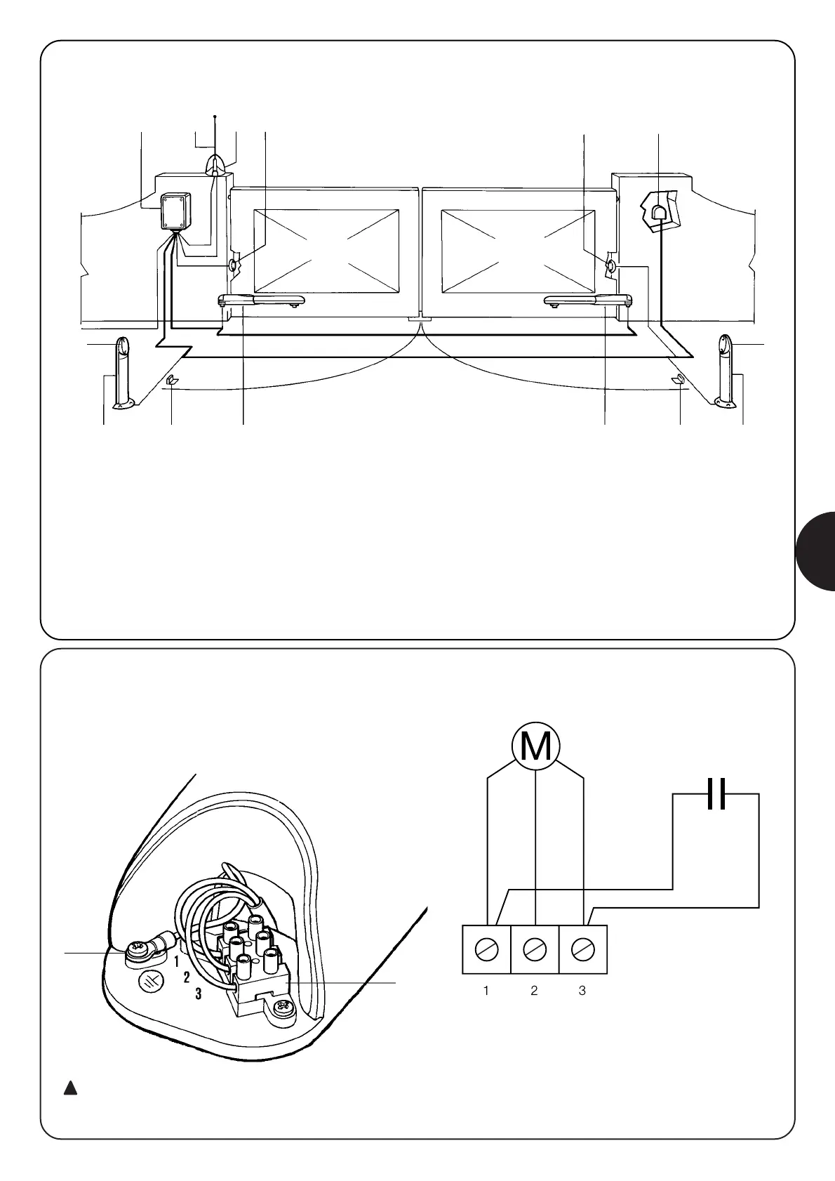
2.4) Instalacja typowa
7
7
3
1
2
8
7
6
5
4
7
1
2
8
9
1 Kolumna na fotokomórki.
2 Blokady przy otwieraniu.
3 Linia elektryczna zasilania.
4 Centrala sterownicza A400.
5 Antena.
6 Lampa sygnalizacyjna.
7 Fotokomórka.
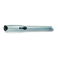
8 Siłownik WINGO.
9 Selektor kluczowy lub klawiatura numeryczna.
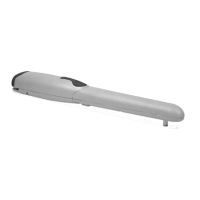
2.5) Podłączenie motoreduktora
Zgodnie z numeracją zacisków wykonać połączenia do tabliczki
zaciskowej (A) według schematu elektrycznego.
A
CZARNY
OTWIERA WSPÓLNY ZAMYKA
5uF
NIEBIESKI
ZIELONY
BIAłY
BIAłY
B
Przypomina się o podłączeniu uziemienia (B) jak
przewidziano w aktualnych normach (EN 60204 - CEI 64-1,
EN 60335)