40
4. Connections
Digitax SF Instruction Manual
5. Descriptions of CN1 Connector Signals
Command Input
Pin No.
26
Interface Circuit
CP(page 47) Control Mode
Signal Description P S T
CMD_PLS
Pulse
A-phase
CCW
Command signal input from the host controller to the drive.
Select command pulse train command signal to input. (No.32.0)
Parameter
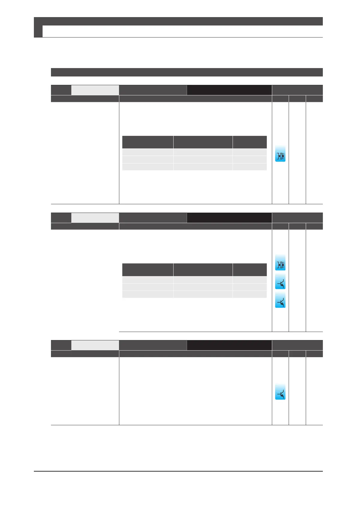
No.32.0
Command Signal Form Input Signal
0
Pulse and Direction Pulse
1
QEP (Quadrature Encoder Pulse)
A-phase
2
CCW and CW CCW
■ Related Parameters
・No.2.0, No.3.0, No,32.0
Pin No.
27
Interface Circuit
CP(page 47) Control Mode
Signal Description P S T
/CMD_PLS
/Pulse
/A-phase
/CCW
Command signal input from the host controller to the drive.
Select command pulse train command signal to input. (No.32.0)
Parameter
No.32.0
Command Signal Form Input Signal
0
Pulse and Direction /Pulse
1
QEP (Quadrature Encoder Pulse) /A-phase
2
CCW and CW /CCW
■ Related Parameters
・No.2.0, No.3.0, No,32.0
5
Pin No.
28, 29
Interface Circuit
CP(page 47) Control Mode
Signal Description P S T
CC-P
(Pin No.28)
CC-D
(Pin No.29)
24V open collector
power
Command signal input from the host controller to the drive.
A power input terminal of 24V open collector.
CC-P:
Use this in combination with /CMD_PLS.
CC-D:
Use this in combination with /CMD_DIR.