33
Connection
Digitax SF Instruction Manual
5. Descriptions of CN1 Connector Signals
4. Connections
5. Descriptions of CN1 Connector Signals
General-Purpose Output
Pin No.
13
Interface Circuit
PO(Page 46) Control Mode
Signal Description P S T
MBRK
Motor Brake Release
Open
Does not release the brake.
Close
Releases the brake.
■ TIP
The motor brake cannot be driven directly. To drive the motor
brake, be sure to use a relay.
Place a surge absorber to suppress surge voltage caused by
relay’
s on/o. Note that, if you use a diode instead of a surge
absorber, the time between brake release and brake clamp is
longer.
䐟
䐠
䐡
䐢
*
ol
䐟
䐠
ol
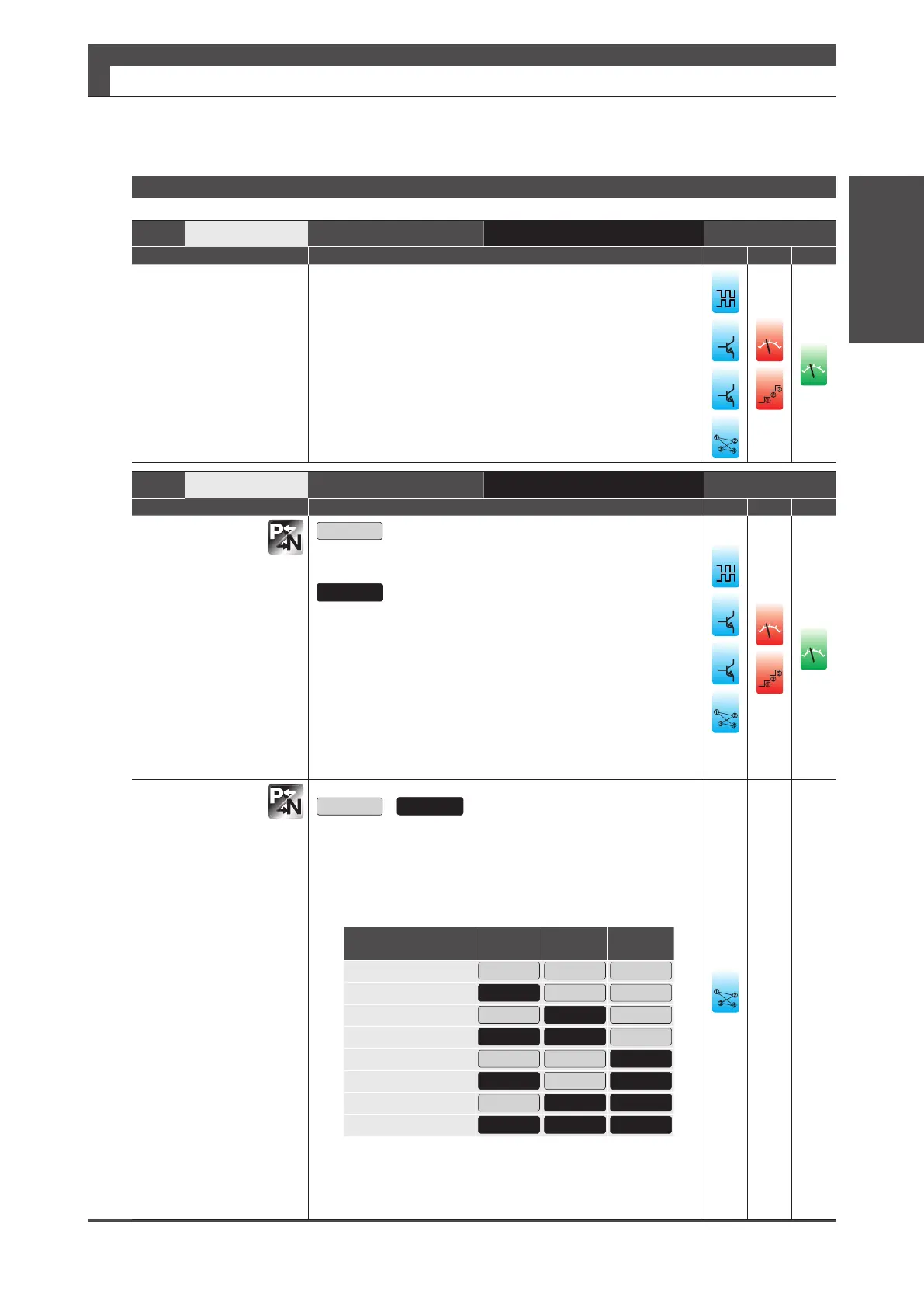
PM1
Point No.1
Open
/ Close
Outputs the started or completed Point No. with a combination
of PM1… PM3.
Right after turning the power on for the drive or at Servo OFF
or Homing, all three are Open (i.e. Point No. = 0).
Point No.
(Pin No.)
PM1
(No.7)
PM2
(No.8)
PM3
(No.9)
0, 8, etc.
Open Open Open
1, 9
Close Open Open
2, 10
Open Close Open
3, 11
Close Close Open
4, 12
Open Open Close
5, 13
Close Open Close
6, 14
Open Close Close
7, 15
Close Close Close
■ Related Parameters
・No.644.0
Enables you to select timing of Point No. output and its
content.
䐟
䐠
䐡
䐢
**
Pin No.
12
Interface Circuit
PS(page 45) Control Mode
Signal Description P S T
COM ー
I/O power GND
A common emitter terminal of output transistors in the general-
purpose output circuit.
COM+ and G24V drive control power must share one
common power supply.
䐟
䐠
䐡
䐢
ol
䐟
䐠
v
ol