F600 Step By Step Guide 20
Communications connections
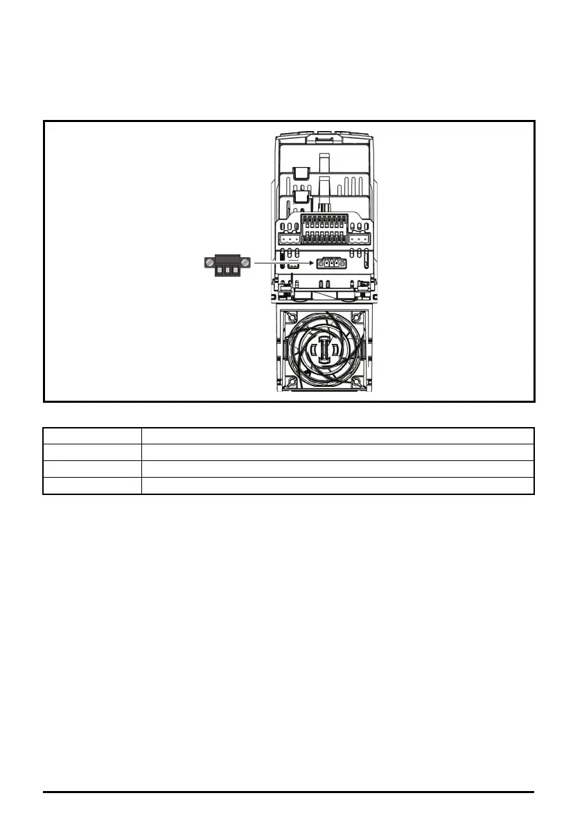
The drive offers a 2 wire EIA-485 serial interface located beneath the control terminals,
see Figure 6-10 Location of the comms connector below. The drive supports the Modbus RTU
protocol as standard. See Table 6-4 for the connection details.
Figure 6-10 Location of the comms connector
Table 6-4 Serial communication port pin-outs
EIA-485 Serial communications
The serial communications port is a 3 way screw type connector, which is isolated from the power
stage and the other control terminals.The communications port applies a 2 unit load to the
communications network.
USB/EIA-232 to EIA-485 Communications
An external USB/EIA-232 hardware interface such as a PC cannot be used directly with the 2-wire
EIA-485 interface of the drive.
To gain access to the drive parameters (including connection to Connect), a KI-485 Adaptor should
be installed as shown in Figure 4-15 and used in conjunction with a suitable USB to EIA-485 isolated
converter. A suitable isolated converter is available from Control Techniques:
• CT USB Comms Cable (CT part number: 4500-0096).
A KI-485 Adaptor is also required for remote LCD keypad operation. The communications cable
between the KI-485 Adaptor and keypad is wired one to one. The maximum cable length is 100 m
when conductors of 0.129 mm² (AWG 26) or larger are used and the cable shield should be
connected to the grounded panel / cubicle at the keypad end of the cable.
Pin Function
1RX TX
2 Isolated 0V
3RX\ TX\
123