10
3
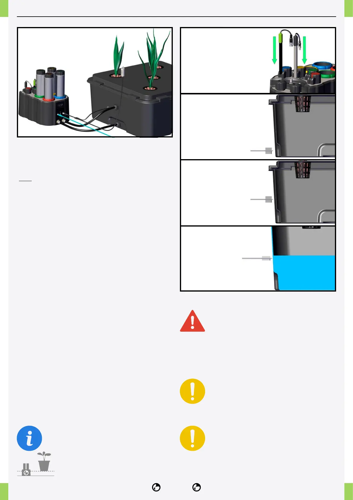
5A
5B
5C
point and all medium and high voltage
electrical outlets including the NIDO plug
must be installed at least 1 metre above the
ground to avoid direct contact with water or
fertiliser.
All low and medium voltage electrical sockets must be
installed away from water splashes.
The temperature/humidity sensor is not
protected against splashing water, so be
careful not to get it directly wet.
Place it at least 1 metre above the ground.
Do not place NIDO ONE V2 and electrical
outlets in a box, any water spillage will
cause danger of electric shock and
submersion and breakage of NIDO ONE
V2.
1� Connect the access point supplied in the kit to an
Ethernet output port on the router/switch and switch
it on. For further details, see the access point section
(p.29).
2� Remove the storage cap from the pH probe.
3� Insert the pH and EC probes into the press-probes
until they are ush. Screw in the press-probes with
light force and connect the appropriate connectors.
4� Insert the fertiliser and pH cans into their slots,
observing the colour of the can and slot labels (green-
yellow-red-blue).
5� Drill the holes for the feed-through and level probe
as shown below:
5A� Drill the IN hole near the bottom of the tank using
the provided bit (30mm bulkhead tting bit) to ensure
water is drawn from the bottom of the reservoir.
5B� Drill the out hole at a point above the maximum
water level. (30mm bulkhead tting bit)
5C� Drill the hole for the level probe (14mm Water
level sensor tip, devices with a serial number starting
with 23... use an 11mm bit) with the centre of the hole
where you want the ALERT water level to be.
The nutrient solution tank must always be placed
higher than the position of the NIDO ONE
V2.
The NIDO ONE V2 power supply, access
NIDO ONE V2 INSTALLATION