Chapter 4 Assembly
112
13
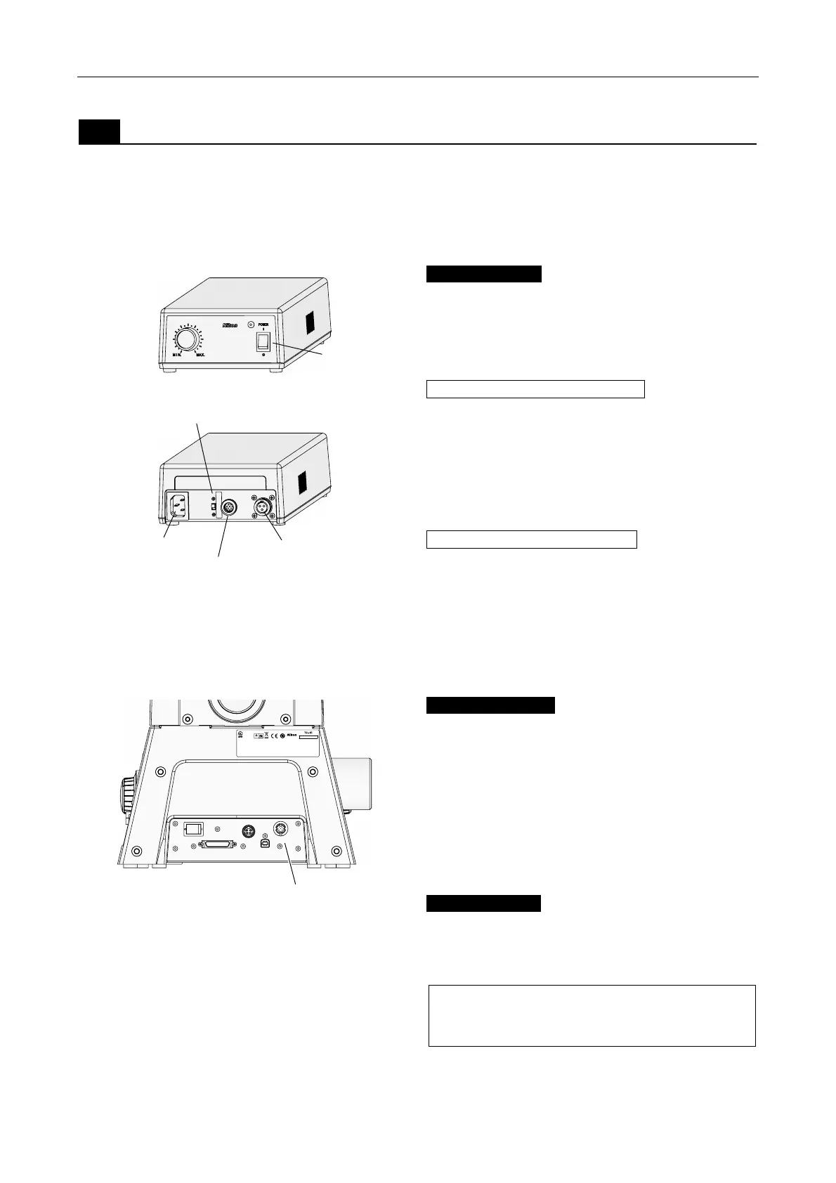
Connecting the power supply device
A power supply device is required to turn on the dia
illumination lamp. Check that the POWER switch on
the power supply device is turned off (pressed on the
“O” side), and then connect the power supply as
described below.
Figure 4-43 Power supply
(1) Lamp cable
Connect the lamp cable from the dia pillar illuminator
to the DC output connector on the power supply
device. A lock ring is provided on the lamp cable
connector. Secure the lamp cable with the lock ring.
For Dia Pillar Illuminator 100W
Connect the lamp cable from the D-LH/LC
lamphouse to the 12VDC output connector on the
TI-PS100W Power Supply.
Before connecting the cable, check that the ferrite
core is properly attached to the connector end of the
lamphouse cable (see page 100).
For Dia Pillar Illuminator 30W
Connect the lamp cable from the dia pillar illuminator
to the 6VDC output connector on the
TE-PS30W/TE-PSE30 Power Supply A.
Before connecting the cable, check that the ferrite
core is properly attached to the pillar end of the
lamphouse cable (see page 101).
MIC CONTROL
POWER
OFF ON
LAMP CTRL
DC24V IN
USB
Gepruftes Medizinprodukt
Approved medical device
Freiwillige Produktprufung
R
5 3 1 0 0 1
This device complies with Part 15 of the FCC Rules.Operation is subject to the
following two conditions:
(1) this device may not cause harmful interference,and
(2)
EQUIPMENT 4N75
MODEL : Ti-E
INSPECTION
TUV
Rheinland
Product Safety
JAPAN
this device must accept any interference received, including interference
that may cause undesired operation.
This Class A digital apparatus complies with Canadian ICES-003.
Cet appareil numØrique de la classe A est conforme la norme NMB-003 du Canada.
Figure 4-44 Ti-E, Ti-E/B (rear view)
(2) Control cable
Connect one end of the control cable to the LAMP
CTRL connector on the rear of the microscope, and
the other end to the EXTERNAL connector on the
TI-PS100W Power Supply or the CTRL connector on
the TE-PS30W/TE-PSE30 Power Supply A.
(3) Power cord
Connect the plug end of the power cord to the wall
outlet, and the other end to the AC inlet connector on
the power supply.
To prevent electric shock, do not connect the
power cord until all other assembly procedures
are completed.
EXTERNAL/CTRL switch
12VDC/6VDC
output connector
AC inlet
EXTERNAL/CTRL
connector
POWER
switch
LAMP CTRL connector