XT V 160 X-ray System XTM0011-F2 23
4 Introduction to the X-ray system
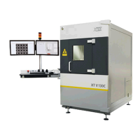
The XT V 160 has been developed utilising X-Tek’s extensive experience in the application
and development of microfocus X-ray technology. The system provides the highest
resolution and magnification possible within a compact system and is ideally suited to
production lines and failure analysis laboratories. Ideal for real-time and automated
inspection of electronics (BGA, μBGA, flip-chip and loaded PCB boards), the XT V 160 is an
easy to use, versatile tool which allows an operator to generate high quality images in a short
time. It provides interactive visualisation and fully automatic X-ray inspection, with optional
Computed Tomography (CT) or X.Tract for in-depth 3D analysis. X.Tract provides CT-quality
inspection of complex, multi-layer electronics assemblies without the need to cut or slice the
assembly.
The system comprises:
• A 160 kV rated lead shielded, steel framed, interlocked safety enclosure with hinged
service access door and integral sample loading door.
• A 160 kV demountable microfocus open transmission X-ray source.
• X-ray spot size: 1 μm
• Defect recognition capability: 500 nm
• Geometric magnification: 2.5x -2,400x
• System magnification: Up to 36,000x
• A five-axis manipulator, with optional CT stage.
• An Inspect-X software controlled workstation.
• Standard imaging system of 1.45 Mpixel 12bit camera with dual field 4"/6" image
intensifier, with Varian 1313 or 2520 digital flat panel imaging options.
4.1 System overview
The system comprises a single enclosure that is separated into two sections. The upper
section is a lead-lined chamber that houses the X-ray source, X-ray imaging components
and a motorised manipulator for moving the sample under inspection. The lower section
includes the electrical controls, power supplies, manipulator drives, X-ray source cooling
pump and vacuum pump. Most of the components in the lower section are located in a
service area at the back of the cabinet.
The X-ray source is mounted inside the lead cabinet. Voltages up to 160 kV DC and power
levels up to 20 W are used to generate the X-ray beam. The beam is directed vertically
upwards, through the sample to be inspected and onto an imaging sensor. The imaging
sensor transmits the image data to a PC for processing and display on a monitor.
A cooling unit mounted in the service area at the back of the cabinet provides a circulating
cooled water supply to the X-ray source. This unit includes a pump, radiator with air-cooling
fan, a reservoir and flow/level sensors. A vacuum ‘backing’ pump located in the service area
is used, in conjunction with a high-speed turbo vacuum pump mounted on the source itself,
to produce the high vacuum inside the X-ray source necessary to generate X-rays.
The 5-axis manipulator inside the cabinet allows the sample under inspection to be moved.
The sample can be moved in the X (horizontal) and Y (vertical) directions and the Z direction
(magnification). The sample can also be rotated and the imaging device can be tilted relative
to the X-ray source. Maximum sample weight is 5 kg (11 lbs).
 Loading...