Introduction to the X-ray system
26 XTM0011-F2 XT V 160 X-ray System
When the INTERLOCK key switch is in the OFF position, it is not possible to generate
X-rays. Always turn this switch to the OFF position and remove the key when performing any
maintenance operations, such as changing the filament in the source.
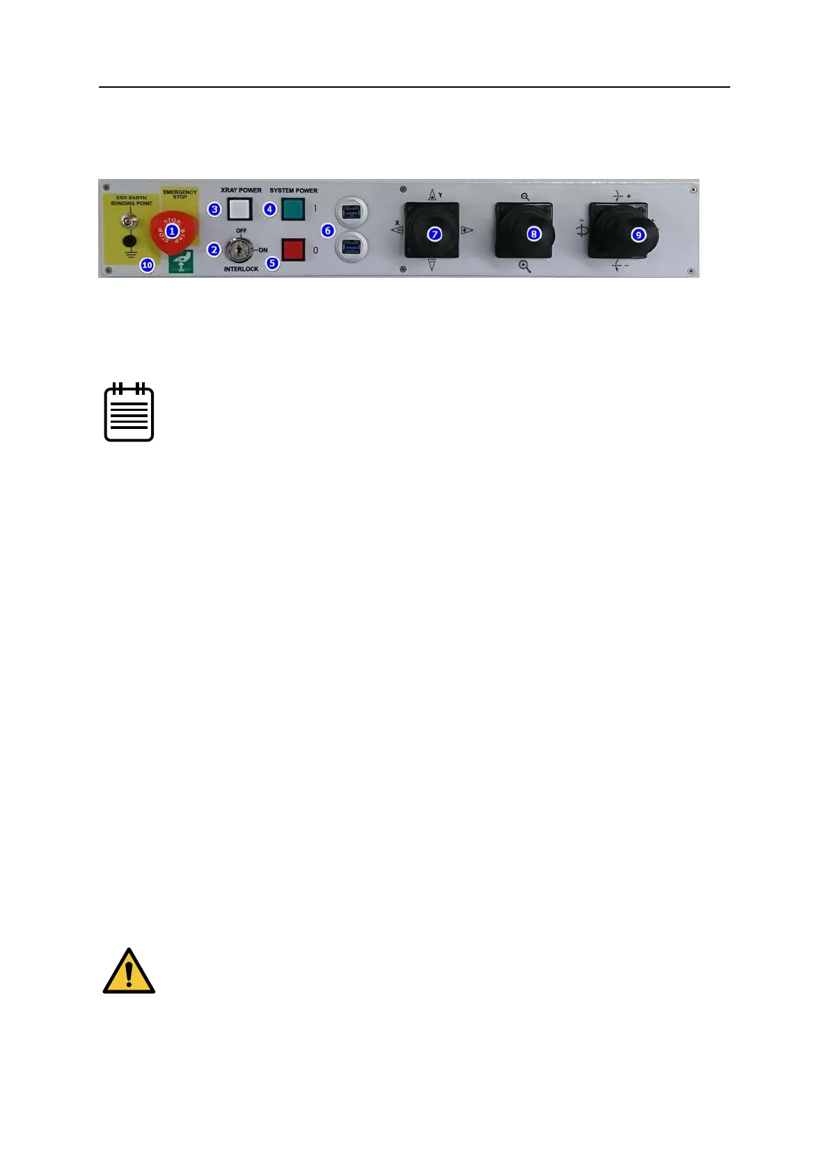
1. EMERGENCY STOP - activated by pushing the red knob fully inwards, when all electrical
power to the machine will be immediately cut (with the exception of the computer to
prevent data loss). After the emergency situation has been resolved, the knob can be
twisted and lifted to restore power. The system must be powered up again before it can
be used.
The emergency stop also forms part of the safety interlock system.
2. INTERLOCK Key – enables (ON) and disables (OFF) X-ray generation; part of the safety
interlock system. The key cannot be removed in the ON position.
3. X-RAY POWER – illuminates white when pressed and applies electrical power to the
vacuum pump circuit. X-rays can be produced as soon as the vacuum reaches a
satisfactory level.
4. SYSTEM POWER On – illuminates green when pressed and applies electrical power to
the main circuits.
5. SYSTEM POWER Off – cuts electrical power to the main circuits when pressed.
6. USB 3 ports - provide easy access for USB devices.
7. X-Y Axis Manipulator Joystick – moves the manipulator table in the +/- X/Y direction as
indicated.
8. Image Zoom Manipulator Joystick – changes the geometric magnification by moving
the sample towards or away from the X-ray source.
9. Tilt/Rotate Manipulator Joystick – tilts the imager or rotates the manipulator table
around the axis indicated.
10. ESD Earth Bonding Point - Allows attachment of electrostatic discharge (ESD)
wristbands or other equipment to earth to avoid static discharge, which may damage
electronic components.
4.3 Monitor and console arm adjustment
To adjust the monitor height, firmly support the monitor with one hand and pull the locking
lever down to release the monitor with the other. Raise or lower the monitor to suit and
re-tighten the locking lever. If the lever is either too tight or too loose adjust with the knurled
nut.
If the monitor is not supported when released, it will drop and tip
forward, possibly resulting in damage to the monitor and/or cables.