15
VPM 3200
Functional diagram VPM 600-3200
910kg 2150kg 910kg
Med fundament: 4 grå 120x120x25 + 4 rød 120x120x25
Uden fundament: 4 grå 100x100x25 + 8 rød 100x100x25 Placeres både front og bag
Placed both front and rear
Placed both front and rear
Placed both front and rear
Placed both front and rear
With base: 8 brown 100x100x25 + 4 red 100x100x25
Without base: 4 red 100x100x25 + 8 brown 100x100x25
With base: 4 red 100x100x25 + 4 grey 100x100x25
Without base: 4 red 100x100x25 + 8 brown 100x100x25
With base: 4 grey 120x120x25 + 4 red 120x120x25
Without base: 4 red 120x120x25 + 8 red 100x100x25
With base: 4 grey 120x120x25 + 4 red 120x120x25
Without base: 4 grey 100x100x25 + 8 red 100x100x25
With base: 4 grey 120x120x25 + 4 red 120x120x25
Without base: 4 grey 100x100x25 + 8 red 100x100x25
Placed both front and rear
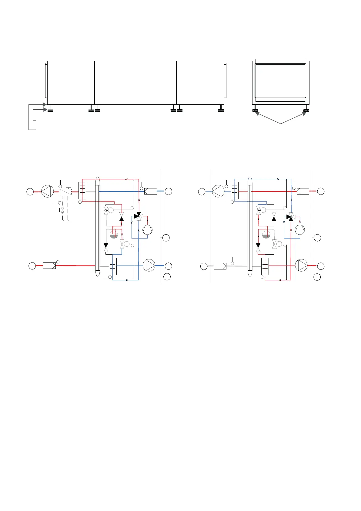
Functional diagram VPM 600-3200
Connections Automation
1: Outdoor air T1: Outdoor air sensor
2: Supply air T2/T7: Supply air sensor
3: Extract air T9: After-heating element frost protection
4: Discharge air T5: Condenser sensor
5: Condensation drain T6: Evaporator sensor
6: Electrical and water after-heating element T10: Room sensor
T5
T10
T6
2
4
6
5
TC
TC
T1
1
3
T2
2
T5
T9
T6
4
6
5
TC
TC
T1
1
3
T2/T7
T10
TC
Heating Cooling
 Loading...