S2 / S3
09/2017
7
C343
GB
Controls and indicators
Figure 5
1. Start/stop switch
2-way selector:
position “0” - The vacuum cleaner is turned OFF.
position “I” - The vacuum cleaner is turned ON.
2. Main motor Start/Stop indicator and button
If the indicator is lit, the main motor is ON.
You can start/stop the main motor with this button.
3. Second motor Start/Stop indicator and button
If the indicator is lit, the second motor is ON.
You can start/stop the second motor with this button.
4. Third motor (S3) Start/Stop indicator and button
If the indicator is lit, the third motor is ON.
You can start/stop the third motor with this button.
5. Stop button
This button stops all the motors simultaneously when pressed
(but doesn’t turn the power of the vacuum cleaner o).
6. Low compressor pressure alarm indicator
If lit, this indicates an anomaly in the pressure of the
compressor (if installed).
7. Max. vacuumed level indicator
If lit, this indicates the maximum level of the vacuumed
material has been reached in the container, if the level
control for liquids or solids is installed.
8. Voltage plate indicator
Indicates the vacuum cleaner is powered.
9. Primary lter indicator
Green - Indicates the primary lter is functioning properly.
Red - Indicates the primary lter is blocked.
10. Absolute lter indicator (if installed)
Red - Indicates the absolute lter is blocked.
11. Manual lter shaker knob (models with manual lter
shaker)
Figure 6
1. Dust container release lever
2. Castor lever
3. Closing band lever
4. Safety bolt (H class)
5. Electric power cable
6. Handle
7. Inlet plug
Figure 7
1. Inlet
Inspections prior to starting
Prior to starting, check that:
■ the lters are installed;
■ all the levers are locked in place;
■ the vacuum hose and tools have been correctly tted to
the inlet (1 - Fig.7);
■ the bag is installed, if applicable.
WARNING!
Do not use the vacuum cleaner if the lter is faulty.
Starting and stopping
Figure 8
WARNING!
Lock the castor brakes (1) before starting the vacuum
cleaner.
■ Turn switch (2) to position “I” to start the vacuum cleaner.
When the switch is in position “I” the motors start in sequence
and the state of the same is shown by indicators (2 - 3 -
4 - Fig. 5).
■ Turn the switch to position “0” to stop the vacuum
cleaner.
Vacuum cleaner operation
WARNING!
The air speed in the suction tube must not be less
than 20 m/s.
This state is shown by the green indicator of the
primary lter.
When using the vacuum cleaner, check:
■ the state of the max. vacuumed material level indicator
(7 - Fig. 5) if the level check is installed.
■ The state of the primary lter (9 - Fig. 5) and the absolute
lter (if installed) (10 - Fig. 5).
■ The state of the low compressor pressure indicator (6 -
Fig. 5) (if installed).
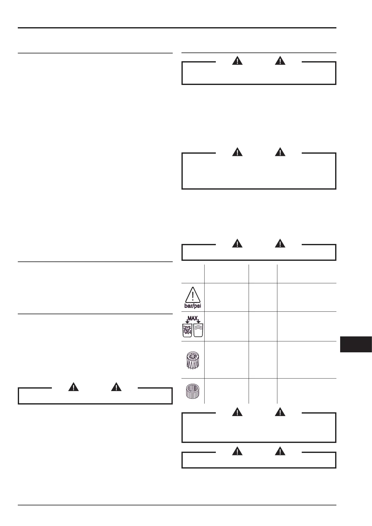
WARNING!
If one of the indicators is lit, follow the instructions.
Symbol Indicator signal
Indicator
colour
Vacuum cleaner state
and procedure
bar/psi
Low compressor
pressure
(6 - Fig. 5)
Red
Suction stopped.
Check the compressor
is functioning properly (if
installed).
MAX
Max. vacuumed
material level
(7 - Fig. 5)
Red
Suction stopped.
Empty the container
(see relevant
paragraph).
Primary lter
(9 - Fig. 5)
Red
Suction on.
Use the primary lter
shaker after stopping
the vacuum cleaner (on
models with a manual
lter shaker).
Absolute lter
(class H models)
(10 - Fig. 5)
Red
Suction on.
Change absolute lter
(see relevant
paragraph).
WARNING!
If the vacuum cleaner belongs to the M or H class,
use only hoses with diameters that comply with the
indications in the Technical data table.
WARNING!
Consult the “Troubleshooting” chapter if faults occur.
 Loading...