14Service Manual – SC900
20 - Wheel System, Traction
Functional Description
The SC900 machine is driven by an electrically
powered transaxle. The transaxle is an open
differential powered by a 1/2 hp, permanent
magnet, 36V motor. A Curtis 1228 solid
state speed controller regulates the speed
and direction of the wheel drive motor. The
motor speed controller is located in the
electrical compartment of the battery bay.
The potentiometer (R1) on the control handle,
controls the speed setting of the machine. The
control handle also contains two forward and one
reverse drive buttons.
Forward and Reverse Switches
Functionally, there are two forward and one
reverse buttons on the control handle. However,
electrically, there are actually three “Go”
switches and a single “Reverse” switch. The
distinction is because the reverse button actually
contains two switches internally, where one
switch is reverse and the second switch is a third
Go switch. The three Go switches are in parallel, so they all act the same.
The three Go switches signal the drive controller to move, and the reverse switch just changes its direction.
The reverse switch by itself will not make the machine move.
The incoming side of the Go switches is connected to the Pot-Lo output from the drive controller, which is at
0 volts. The output side of the switches is connected to the throttle input of the drive controller, and also the
low side of the speed limit potentiometer.
The incoming side of the reverse switch is connected to the key switch output. When the key switch is turned
on, the reverse switch receives 36 volts. When the reverse switch is also closed, this 36 volts is provided to
the “Reverse” input of the drive controller, which signals the controller that when it operates, it should be in
the reverse direction.
Speed Limiting Potentiometer
The speed limiting potentiometer (R1 pot) is a 3-wire variable resistor connected to the Speed Limit input
of the drive controller. This pot sets the upper speed limit of the controller so that when any Go switch is
closed, the machine is set to full-throttle, but this potentiometer limits the speed.
As a 3-wire potentiometer, the Drive Controller sets the bias voltage to the potentiometer. However, The
normal “Pot Low” bias voltage rst passes through the Go switches. So the speed limit potentiometer is out
of the circuit until one of the Go switches is closed. When the Go switches are open, the Speed Limit wiper
voltage will be nearly 5 volts, but as soon as one of the switches closes and the pot is properly biased, the
wiper voltage will immediately drop to its expected voltage via voltage division between Pot-Lo and Pot-Hi.
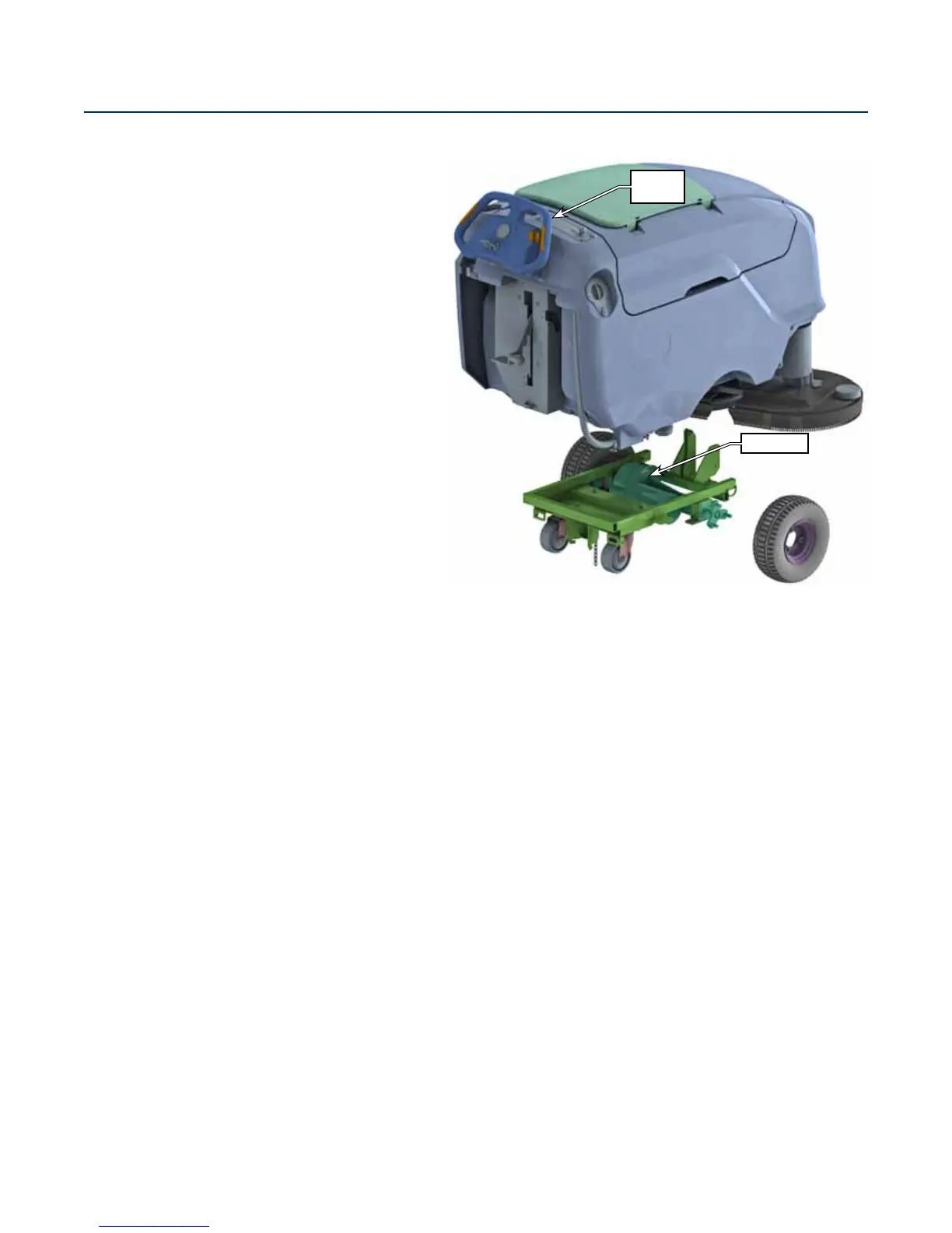
Control
Handle
Transaxle

 Loading...


