20Service Manual – SC900 20 - Wheel System, Traction
Removal and Installation
Drive Controller
WARNING: Unswitched battery power is present at the drive controller. Disconnect the battery
connector before servicing the machine.
Note: Drive controllers are factory pre-programmed for the specic machine. Use only factory
authorized replacement controllers.
1. Drain the recovery tank and open the
recovery tank to access the battery bay.
2. Turn off the key and disconnect the main
battery connector.
3. Remove the Electrical Bay Cover described
on page 33.
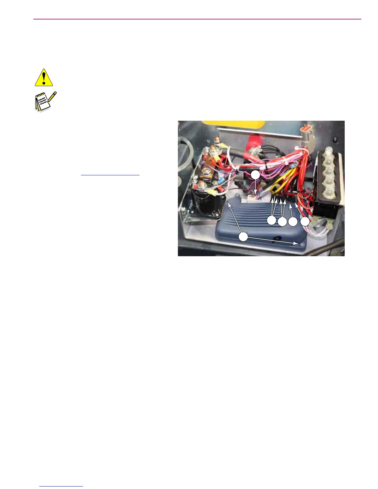
4. Disconnect the logic connector (A) from the
drive controller.
5. Disconnect the high power wires as follows:
• Two motor-negative (Yellow/Black)
• Two motor-positive (Red/Green)
• Battery-negative (Black)
• Battery positive (Red)
6. Remove the two mounting screws (C), and remove the module.
7. Reverse the steps to install a new module.
Follow-up Testing
After replacing the drive controller, perform this follow-up testing procedure to ensure safe operation of the
controller.
1. Before reconnecting the battery, either block the wheels off the ground or move the machine to an open
area without obstructions.
2. Turn the speed dial all the way to its lowest speed.
3. Reconnect the battery connector and turn on the key switch.
4. While holding any of the drive switches, slowly increase the speed limit dial up and back down to verify
complete speed range.
5. Test both forward and reverse directions.
6. Lower the scrub deck and verify the scrub function, which is controlled by the drive controller.
A
M-
M+
B-
B+
C

 Loading...


