37
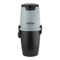
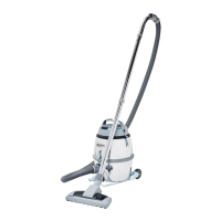
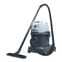
5 Vacuum unit Silver/Sopra 160 / Gold/Sopra 260
Gold RRC/Sopra 260 RRC assembly instructions
5.1 Fitting the wall bracket
Plan the positioning of the wall bracket so that there is plenty of
space above and below the area where the vacuum unit is to be
located. Make sure there is a minimum of 200 mm free space
below the dust container.
Mark the positions for all four screw holes with a pen or similar.
The diameter of the holes in the holder is 5 mm. Select screws
and, if necessary, wall plugs suitable for the type of wall
concerned. Drill the four screw holes.
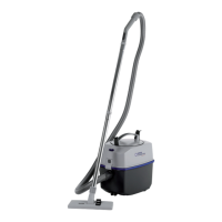
Fit the wall bracket with the large opening pointing downwards,
see Fig. 14. Then screw the holder fi rmly into place.
5.2 Locating the vacuum cleaner on
the wall bracket
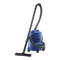
To facilitate the procedure, fi rst remove the dust container.
Free the container by pulling both handles outwards. Then
remove the container from the machine.
To mount the
vacuum cleaner/motor chassis to the wall bracket - just lower
the chassis downwards so that the locking device of the bracket
will pass through the slot of the chassis
Fig. 15. Make sure the
corresponding bracket on the machine is held fi rmly in place by
the wall bracket.
When removing the motor chassis from the wall bracket - push the
locking device towards you so it will release the chassis and then lift
the chassis up from bracket.
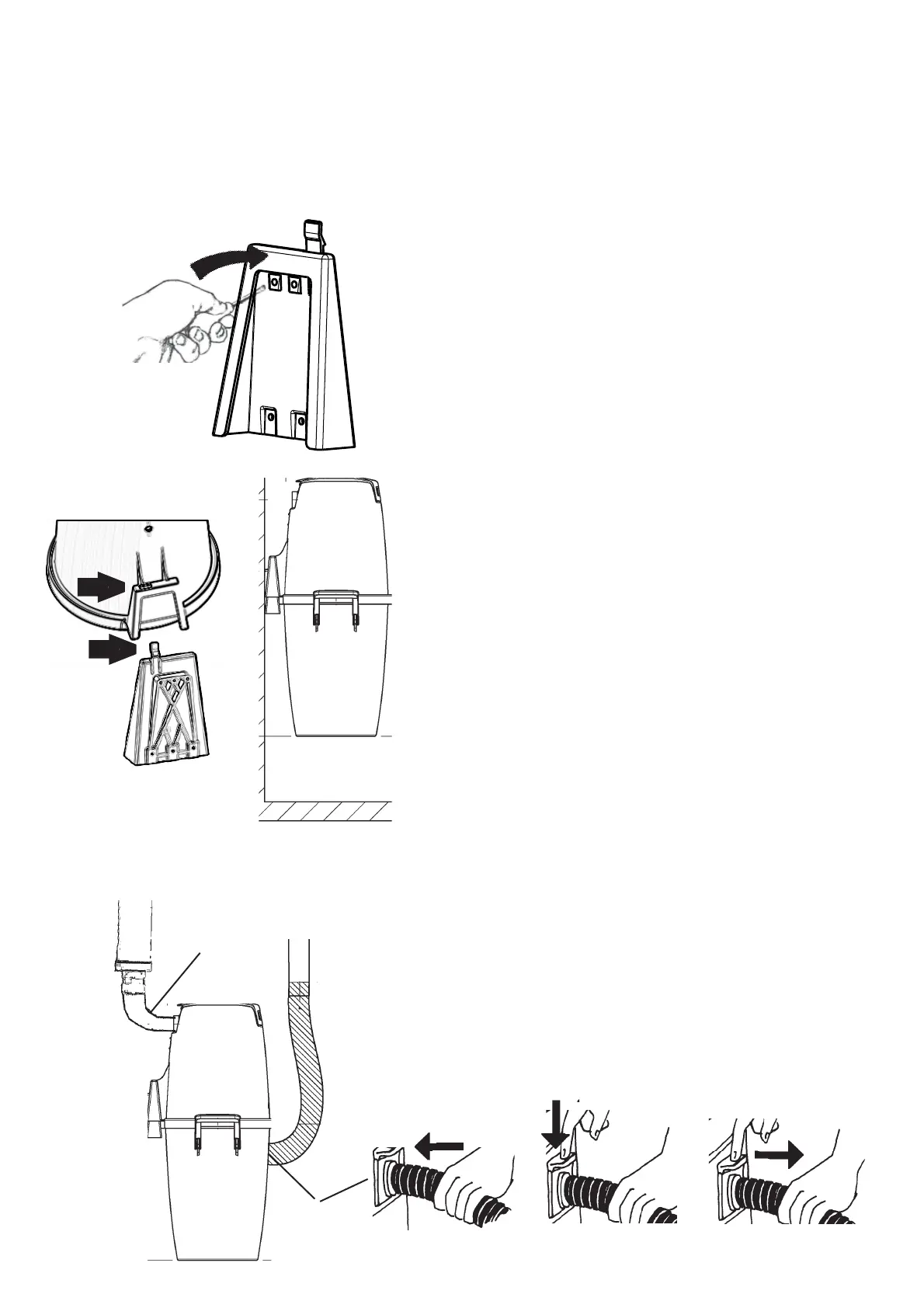
5.3 Connecting the machine
The machine is connected with the fl exible suction hose in the
lower position and the exhaust pipe uppermost, Fig 16. The
fl exible hose is connected to the dust inlet at the container of
the cleaner.
Push the hose in to the inlet at the cleaner until the
hose locks. Press the button on the hose inlet downwards in order
to remove the suction hose.
The fl exible suction hose acts as an
adapter connecting the vacuum unit with the pipe system.
NB! These connections must not be glued in case the unit
is handed in for service.
Position the central vacuum cleaner so that the exhaust pipe
can be kept as short as possible, maximum. 5 metres. Take the
surroundings into consideration when positioning the exhaust.
For this reason, you should always fi t a muffl er.
For additional information concerning the assembly and
installation of the pipe system and low-current lead, please refer
to the separate assembly instructions supplied with the pipe
package.
Exhaust
Inlet
Fig. 16
Fig. 14
Push the hose in to the inlet at the cleaner until the hose locks.
Press the button on the hose inlet downwards in order to remove
the suction hose.
 Loading...