ENGLISH USER MANUAL
30 SW4000 - 1464809000
FUSE CHECK/REPLACEMENT/RESET
1. Drive the machine on a level ground and engage the
parking brake.
2. Turn the ignition key (61) to “0”.
3. Open the battery compartment hood (18) with the handle
(41) and fasten it with the support rod (52).
4. Disconnect the battery connector (45).
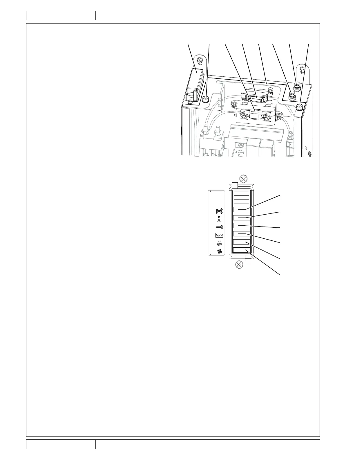
Lamellar Fuse Check/Replacement
5. 5HPRYHWKHIXVHER[FRYHU$)LJ
6. Check/replace the relevant fuse among the following (Fig.
23):
(B): F1 vacuum system motor fuse (25 A).
& )¿OWHUVKDNHUPRWRUIXVH$
(D): F3 display electronic board fuse (3 A).
(E): F4 main fuse (key circuit) (10 A).
(F): F5 dust guard system fuse (5 A) (optional).
(G): F6 hopper lifting fuse (25 A).
7. Remove the screws (H, Fig. 20), then remove the cover (I)
RIWKHHOHFWULFDOFRPSRQHQWER[
8. Check/replace the following fuses:
(J): FA main broom motor fuse (50 A).
(K): F0 main fuse (150 A).
Fuse Check
9. Check one of the following fuses (Fig. 22) for deactivation:
(L): FR1 right side broom motor fuse (15 A).
(M): FR2 left side broom motor fuse (15 A) (optional).
Reset any deactivated fuse, when the component that
caused deactivation has fully cooled down.
Reassembly
10. Connect the battery connector (45).
11. Remove the support rod (52) and close the hood (18).
A H K LMJ I H
P100609
Figure 22
B
C
D
E
F
G
25A
5A
10A
3A
25A
25A
P100610B
Figure 23
SAFETY FUNCTIONS
The machine is equipped with the following safety functions.
EMERGENCY PUSH-BUTTON
It is to the left side of the operator (79). It has to be pressed in case of emergency, to stop all the machine functions.
DRIVER’S SEAT MICROSWITCH
It is located inside the driver’s seat (3) and it does not allow the machine drive system to operate if the operator is not seated on the
driver’s seat.
HOPPER POSITION SENSOR
When the hopper is lifted, the sensor reduces the machine speed, turns off the vacuum fan and stops the broom rotation.
HOPPER SAFETY VALVE
When the hopper is lifted, the safety valve on the hydraulic lifting cylinder prevents the hopper to accidentally lower.

 Loading...