© 2005-2016 Nira Control AB 16
2.3 Measurement Principles
All engine management systems have to determine engine position and
calculate the correct mass of fuel to inject for a given mass of air. The masses
of the fuel and air vary with temperature and pressure.
2.3.1 Angular positioning
The engine angular position of the crank shaft is crucial for accurate engine
control.
The most common types of sensors used for angular positioning in
automotive applications are
Hall sensor
Inductive sensor
Hall sensor
The Hall Effect is based on a magnetic field that affects electrons moving in a
conductor. The sensor is in need of power supply and the output is a square
wave with fixed voltage levels. The output level is equal or less the supply
voltage.
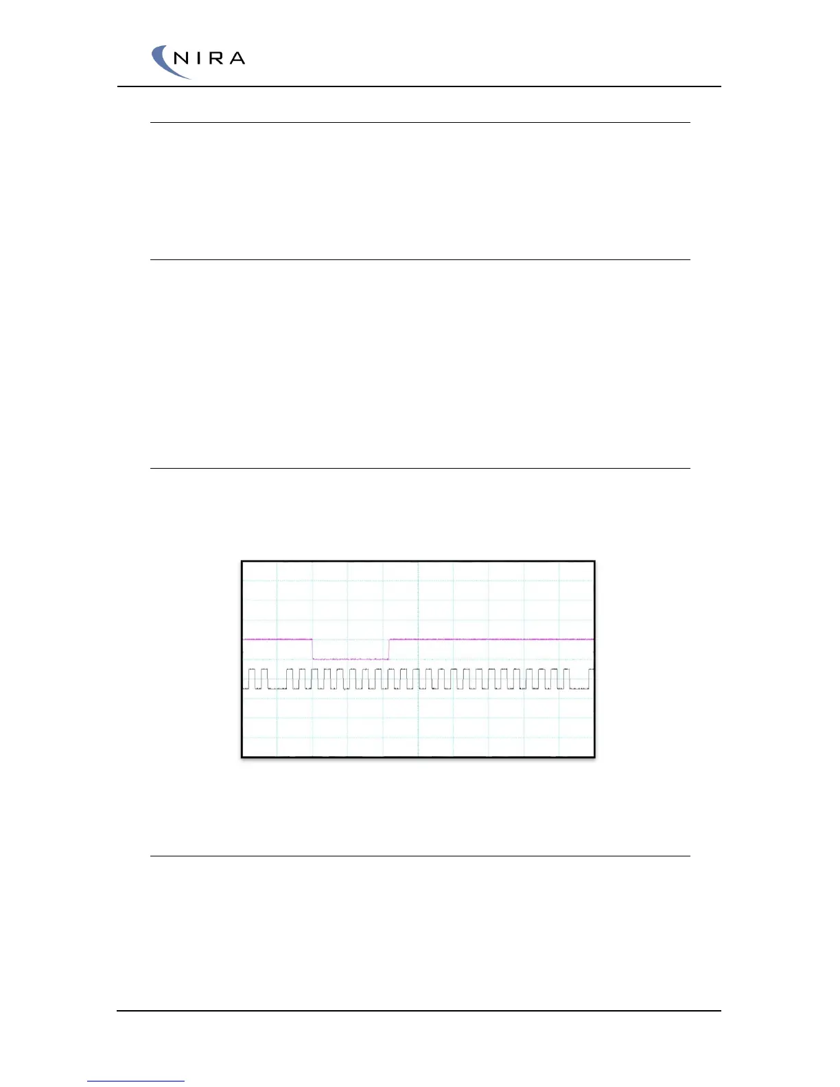
Example of CKP & CMP hall sensors plotted over one revolution. “CKP is a 24-1 pattern”
Inductive sensor
The inductive sensor or VR sensor (Variable Reluctance) uses the
phenomenon of induced voltage in the sensor. The voltage is induced when
ferrite steel passes the sensor and changes the flux through the sensor’s built
in magnet. Therefore the sensor is not in need of any power supply. The
output voltage from the sensor will go from negative to positive values. The
output levels from the sensor will increase proportionally to the speed of the
tooth passing the sensor.