© 2005-2016 Nira Control AB 28
3.4 Manifold Absolute Pressure (MAP) and
Intake Air Temp (MAT)
When NIRA i7x is set up as a speed density system,
precise knowledge of both the absolute pressure and the
air temperature in the intake manifold are required in
order to calculate the correct amount of fuel to inject.
If your vehicle already has MAP and MAT sensors you
may be able to use those. The MAT sensor will need to react very quickly to
sudden changes in temperature. This is especially important on a turbo
charged engine where the intake air temp can increase 100 degrees Celsius
within a few seconds.
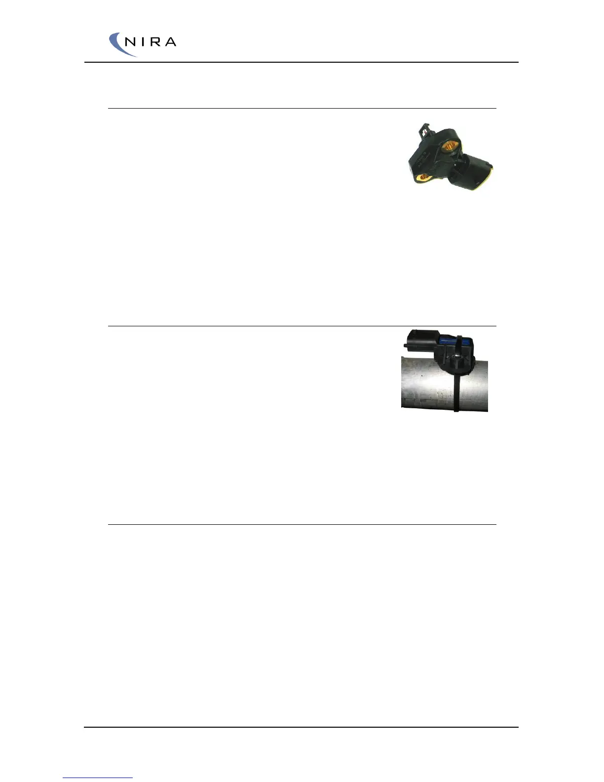
Your NIRA i7x dealer sells an appropriate combined MAP-MAT sensor. This
sensor is pre-calibrated in the NIRA rk software.
3.4.1 Mounting the MAP/MAT Sensor
The NIRA i7x MAP/MAT sensor mounts on a horizontal
surface on top of the intake manifold after the throttle
butterfly. (For manifolds with multiple butterflies, see
3.4.2 below.) Drill a 12 mm hole and mount the sensor
with the sensing element pointing down in order to
avoid accumulation of droplets on the sensing
element. When you drill the hole, make sure to
vacuum up all shavings. Any shavings left inside
the manifold can cause significant damage to
the engine.
3.4.2 Multiple Throttle Butterflies
If each intake runner has an individual throttle butterfly you can still use a
single MAP/MAT sensor provided you build a small, external plenum and
attach the MAP/MAT sensor to it. The plenum volume should be around 200
ml. Connect the plenum to each individual intake runner, after the throttle
butterfly, using hoses with restrictions. Make sure the restrictions are all the
same size.
With this setup you can still use speed-density mapping, which offers greater
accuracy and stability than using only the throttle angle (Alfa-N mapping),
despite MAP fluctuating at low rpm’s. Calibration is done by changing the
inner diameter of the restrictions. Measure the MAP signal at NIRA i7x with
an oscilloscope. The MAP signal is between pins E.12 and and E.53 of the