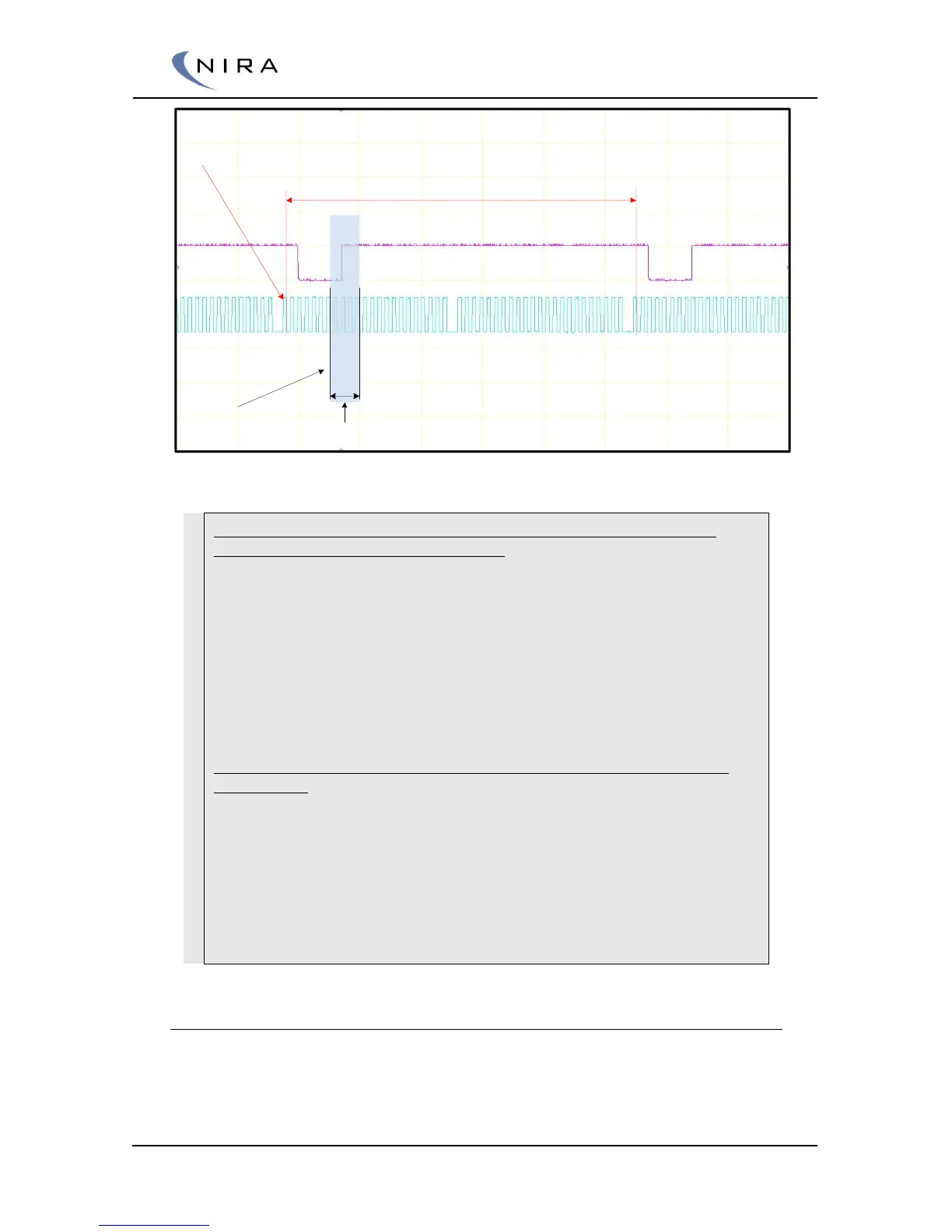
Scope picture of 24-1 crank wheel and a cam wheel with one tooth
Example. The picture shows a scope picture of two crank revolutions
with Hall sensors at both crank and cam.
It is a 24-1 wheel. Every tooth is 360/24 = 15 degrees/tooth
Tpu Crank Lost Teeth should be set to 1
Tpu Crank Polarity is Falling. The system looks for the first falling edge
after the lost gap. (see red vertical lines)
Tpu Crank Sensor Select should be set to Hall
Tpu Crank Total Teeth should be set to 24-1 = 23
The blue opaque field shows an area where the cam shaft sensor gives
a rising edge
Tpu Cam Sensor Select should be set to Hall
Tpu Cam Window Start correspond to teeth nr 6: 6 * 15 = 90 degrees
Tpu Cam Window With correspond to teeth nr 4: 4 * 15 = 50 degrees
Tpu Cam Polarity correspond to the cam signal transition from low to
high level within the blue field: Rising
5.1.2 Engine Setup -> Engine Specifications
Engine Specifications is related to the engine hardware. Values entered in
this section are used for air mass, fuel mass calculations and cylinder
individual timing.