© 2005-2016 Nira Control AB 74
done this, enter a rough, basic ignition map or use the map in the default
data set that comes with NIRA rk.
The offset is a constant and rarely has any significance beyond it’s function as
a basic reference. Use a timing light and check the angle at a specific RPM
and then compare this value to Cyl 1 from 2 lost if you do not already know
what the offset is on your particular engine.
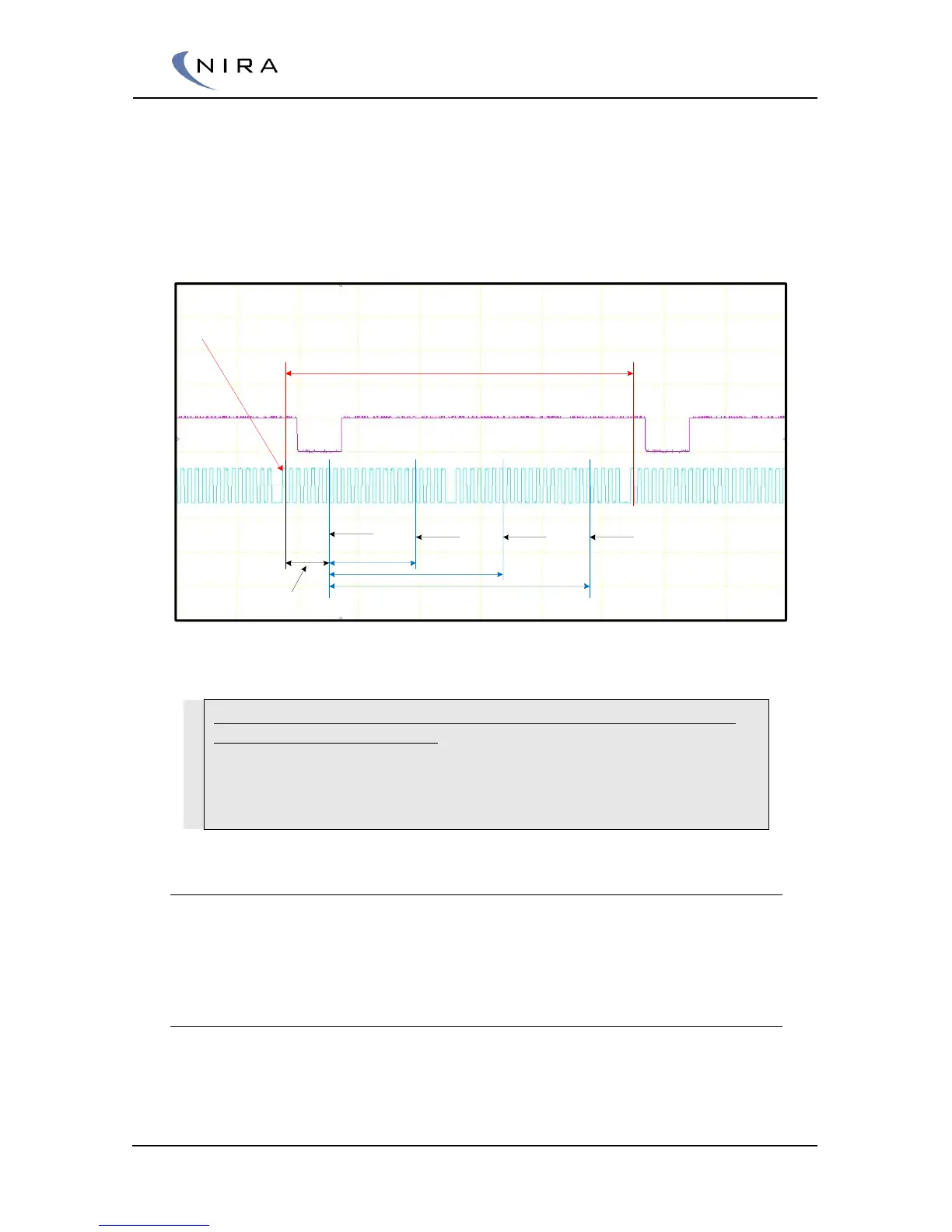
First teeth
Two revolutinos, 720 degrees
Tdc Cylinder Offset
Cyl 1 TDC
Cyl 3 TDC Cyl 4 TDC Cyl 2 TDC
Bv Tdc Cylinder
Example of a four cylinder engine with symmetrical firing order 1-3-4-2 and 90 degrees
offset to tdc at cylinder 1.
Example. The picture shows a scope picture of two crank revolutions of
an inline, four cylinder, engine.
It is a 24-1 wheel. Every tooth is 360/24 = 15 degrees/tooth
Bv Tdc Cylinder Offset. In this case the relationship between crank
wheel mounting made the offset to 90 degrees (6 teeth).
5.1.3 Engine Setup -> Fuel injectors
The fuel injector parameters are used to calculate the injector opening time
based on the requested fuel mass.
Injector offset
In NIRA rk there’s a table called Injector offset. This is the injector dead time
at different battery voltages. This table is important to adjust correctly down
to 0.1 milliseconds. The table gives NIRA i7x information about where the