3.2.1 Base Foundation
The steel bar, concrete mark and mix ratio in the forming process of the base foundation
shall be constructed strictly according to the design drawing. The foundation vibration
reduction device shall be installed according to the requirements of the drawing (if
necessary).
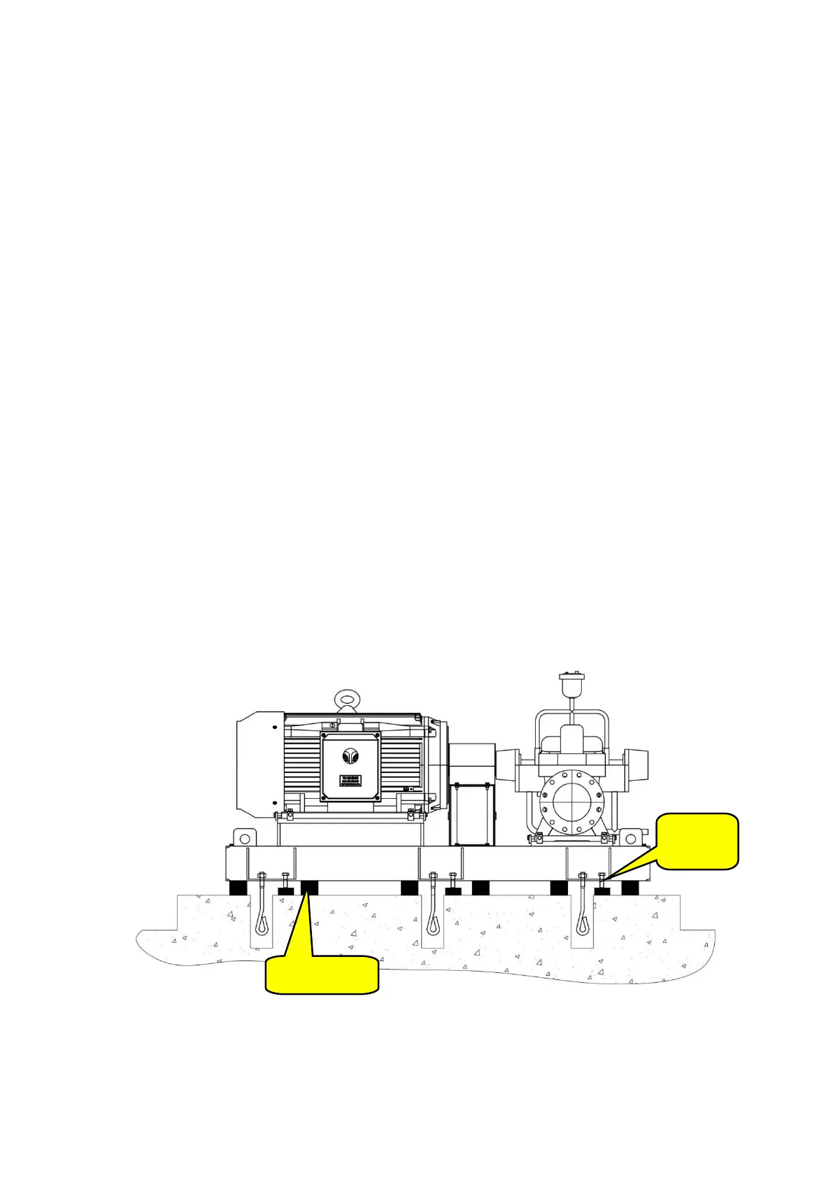
3.2.2 Anchor Bolt and Sizing Block
1. Before installation, the pump room design and installation drawing should be read
carefully by installation personnel. The non-perpendicularity of the anchor bolt shall not
exceed 1/100; The outermost edge of the anchor bolt should be more than 15mm away
from the grouting hole wall; The bottom end of the bolt should not touch the bottom of
the hole; Grease and dirt on the anchor bolt shall be cleaned, but the threaded part
connected with the pump on the grouting hole shall be coated with grease. The contact
between the anchor bolt fastener and the equipment base shall be good; After
tightening the nut, the bolt must expose 1.5 ~ 5 pitch of the nut.
2. The flat sizing block should be placed under the equipment base to bear the main load
and strong continuous vibration; The outer edge of the equipment base shall be
exposed by the sizing block of 10 ~ 30mm, and the length of the sizing block extending
into the equipment base shall exceed the bolt hole of the equipment foundation. Each
sizing block group should reduce the block number as far as possible, general should
not exceed 3, and make less use with thin sizing block; when placing flat sizing block, the
thickest is put below, the thinnest is put in the middle, and should weld each block each
other firmly, but cast iron can not be welded, each sizing block should be placed neatly
and smoothly. After the equipment is leveled, each sizing block shall be compressed.
(see pump installation manual for more detailed installation requirements)
FIGURE A.3.2.2(A)Anchor Bolt and Sizing Block