3.4 Discharge Pipe of Fire Pump Line
3.4.1 Discharge pipe of the motor fire pump
1. The discharge pipe size of the motor fire pump must meet the output requirements at
150% rated flow;
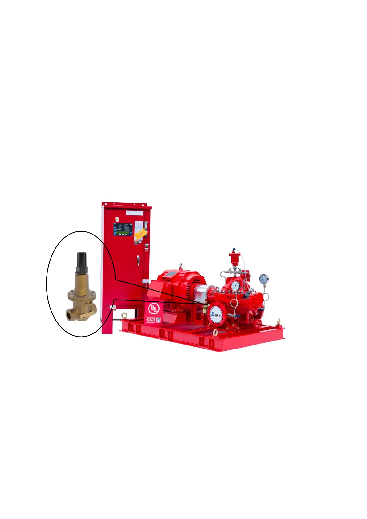
2. The circulation safety valve must be installed between the discharge of the motor fire
pump and the check valve, to prevent the fire pump from burning when it runs at 0%
rated flow for a long time.
3. Do not install the valve before and after the circulation safety valve connection line, the
valve discharge line is connected to the waste water collection ditch;
4. In order to avoid the pipe, valve weight and pipe thermal stress generated by the force
and torque exceeding the maximum allowable external load of the pump inlet and outlet,
the pipe support must be installed on the suction and discharge pipe.
FIGURE A.3.4.1 Installation of circulating safety valve
3.4.2 Discharge pipe of the diesel fire pump
1. The discharge pipe size of the diesel fire pump must meet the output requirements at
150% rated flow;
2. Safety pressure relief valve must be installed between the discharge of the diesel fire
pump and the check valve, to prevent damage to the pipe network caused by the pipe
network pressure exceeding the pipe network bearing pressure capacity when the pump
overspeed;