4.3.2 Start Running
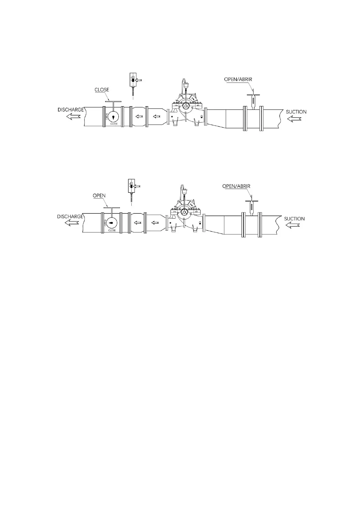
1. Close the valve at discharge side, and open the valve at the suction side.
2. After the diesel fire pump starts, slowly adjust the engine throttle to improve the engine
speed, and slowly open the drainage valve to check whether the discharge pipeline leaks.
If no leakage, adjust the engine speed to the pump rated flow and head.
5.0 FIRE PUMP SYSTEM CONTROL LOGIC
In different fire control systems with different number of fire pump, the operation is also
different, the following we take the most common used system of one motor pump as the
main pump, one diesel pump as a backup pump, and one jockey pump to illustrate its
control logic;
Example 1: normally the jockey pump pressure is "9bar ~ 10bar" to maintain the pipe
network, the starting low pressure of the motor fire pump and the diesel fire pump is set at
"8.5bar", the low-pressure delay starting time of the motor fire pump is "0 s", and the
low-pressure delay starting time of the diesel fire pump is "12 s". (Time difference control
mode)
Example 2: normally the jockey pump pressure is "9bar ~ 10bar" to maintain the pipe
network, the starting low pressure of the motor fire pump is set at "8.5bar", the starting low
pressure of the engine fire pump is set at "7.5bar". When the jockey pump cannot maintain
the pressure of the pipe network, the pressure drops to 8.5bar and the motor fire pump
starts. If the motor fire pump starts or fail start, the fire pipe network pressure drops to
7.5bar diesel fire pump starts. (pressure difference control mode)