3.9 Fire Pump Controller Pressure Sensing Line
1. For all fire pumps, including jockey pumps, each controller shall have its own separate
pressure sensing line;
2. Pressure sensing pipe must be made of hard brass or not less than 300 stainless steel,
pipe diameter is 1/2" (15mm).
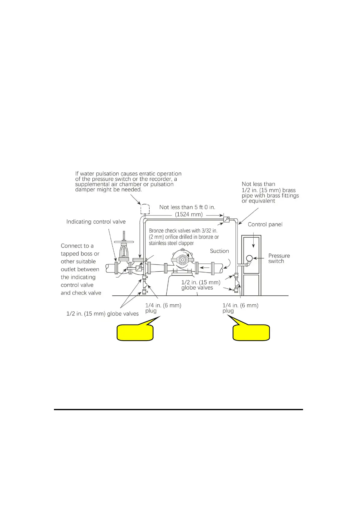
3. Install two check valves in the pressure sensing line, the installation distance of check
valve must be 1.5m, and drill a 2.4mm (3/32") through hole on the disc of check valve.
Pay attention to the installation direction of these two check valves.
4. Install two inspection test valves in the pressure sensing line;(see figure 1 and figure 2 )
5. The pressure sensing pipeline of each fire pump is connected between "check valve" and
"globe valve" at the outlet of the pump.
Notes:
1. Solenoid drain valve used for engine-driven fire pumps can be at A,B,or inside controller
enclosure.
2. If water is clean,ground-face unions with noncorrosive diaphragms driled for 3/32
in.orifices can be used in place of the check valves.
FIGURE A.3.9(A)Pressure Sensing Line