50
STANDS & COMPONENTS
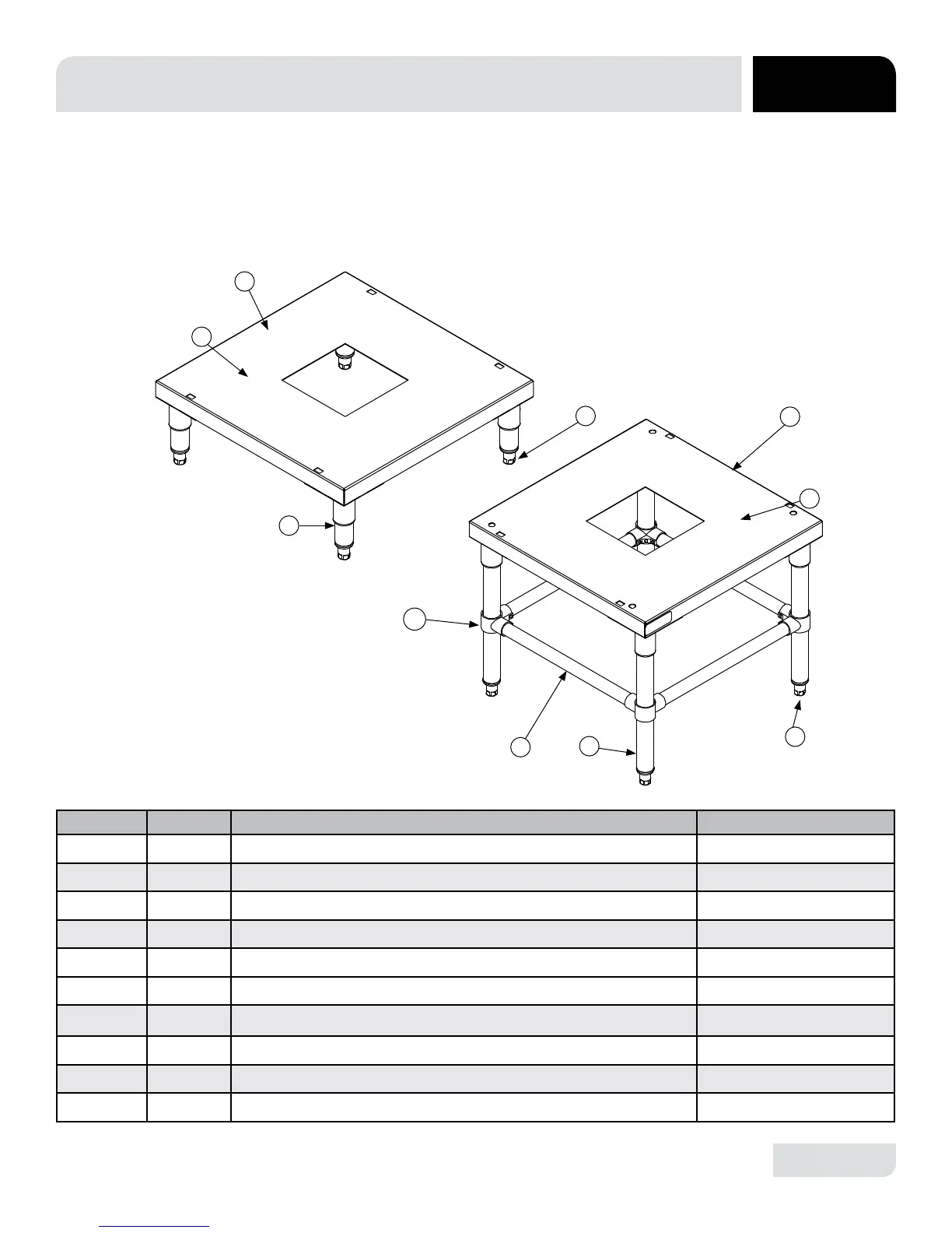
PARTS
To install the stand, rst remove the adjustable feet from the machine. Place machine
on table and use the square mounting holes to line up the machine. Re-insert the
adjustable feet through bottom of table top and tighten to lock machine to table.
INSTALLATION
INSTRUCTIONS:
ITEM QTY DESCRIPTION PART NUMBER
1 1 6” Stand Assembly 05700-003-34-24
2 1 Stand 05700-002-88-82
3 4 6” Leg 05700-021-61-10
4 4 Bullet Foot 05340-108-01-03
5 1 18” Stand Assembly 05700-003-34-25
6 1 Stand 05700-002-88-82
7 4 Bullet Foot 05340-108-01-03
8 4 18” Leg 05700-002-89-47
9 4 Cross Brace 05700-003-25-90
10 4 Cross Member Bracket 04730-003-25-89
1
2
3
4
5
10
9
8
7
6