Installation
3-1
E1999 Nordson Corporation
All rights reserved
104 330H
Issued 8/99
Manual 1-8
Section 3
Installation
WARNING: Allow only qualified personnel to perform the
following tasks. Follow the safety instructions in this document
and all other related documentation.
WARNING: All system components must be grounded,
including the pump. Failure to provide a secure ground could
result in a fire or explosion caused by a discharge of
staticelectricity.
Figure 3-1 illustrates a typical single gun, heated, circulating system.
Multiple gun systems typically use a dual filter after the pump, a bank of
heaters before the first gun in the system, and a filter before each gun.
Additional heaters can be added after each gun to maintain material
temperature. Dead-end (non-circulating) systems are usually cold
systems that would use only the filter(s), with parallel fluid lines to the gun
from the filter(s).
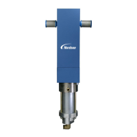
When installing the 25B pump on a wall, stand, or dolly, there should be
at least 508 mm (20 in.) of clearance at the bottom of the pump. The
installation area should be accessible for operation and servicing.
The diameter of the optional wall mounting bracket bolt holes is 8.36 mm
(0.34 in.) on 152.4 mm (6 in.) centers.
NOTE: An approved pressure relief valve set at 6.9 bar (100 psi) must
be installed in the inlet line to this pump.
NOTE: If an optional mounting kit was ordered, first install the air intake
fitting included with the pump to the air inlet port. The air intake fitting
has an internal screen that will prevent contaminants from damaging the
air valve or motor.
1.Install the air fitting, regulator, and gauge, furnished in the optional
mounting kit, to the
3
/
8
NPT air inlet port at top right side of air motor.
2.Install an air shut off valve, drop leg, and water drain valve in line
before the regulator.
1. Introduction
2. Wall or Dolly Mounting
3. Air Connections

 Loading...