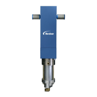
Installation
3-3
E 1999 Nordson Corporation
All rights reserved
104 330H
Issued 8/99
Manual 1-8
CAUTION: Use Nordson, equivalent nylon, or Teflon hoses
with electrical continuity between the fittings. They must
withstand a maximum working pressure of at least 172 bar
(2500 psi). They should have a minimum ID of 6.4 mm (
1
/
4
in.).
Do not use pipe in a high pressure circuit. As an alternative,
use seamless steel tubing, 9.5 mm (
3
/
8
in.) x 0.87 mm
(0.035 in.) wall.
1. Connect the proper hydraulic fitting to the
3
/
4
NPTF port at the bottom
of the siphon housing.
2. Connect the siphon hose, siphon rod, and siphon strainer to fitting.
NOTE: The pressure hosing outlet port size for 2:1 and 4:1 pumps
is
3
/
8
NPTF. The pressure hosing outlet port size for 16:1 and
27:1 pumps is
1
/
4
NPTF.
3. Connect a high pressure fluid hose to the pressure housing
outlet port.
4. Depending on your installation, connect the high pressure fluid hose
to the fluid heater or filter.
4. Hydraulic Connections
Non-Circulating Systems

 Loading...