Repair
7-16
E1999 Nordson Corporation
All rights reserved
104 330H
Issued 8/99
Manual 1-8
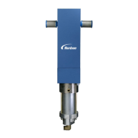
See Figure 7-6. Use the following procedures to repair 16:1 and 27:1
hydraulic sections.
See Figure 7-6. Use the following procedure to disassemble the
hydraulic section.
1.Remove the hex head cap screws and lockwashers that secure the
solvent chamber to the air motor lower head. Pull the hydraulic
section away from the air motor until the bottom of the connecting rod
and the top of the plunger are exposed.
2.Place wrenches on the flats of the connecting rod and plunger. Hold
the connecting rod and turn the plunger counter-clockwise until the
plunger and connecting rod are separated.
3.Remove the hydraulic section and place it on a clean work surface.
Remove the hex head screws (3) and lockwashers (4) securing the
solvent chamber (1) to the high pressure sleeve (6). Remove the
solvent chamber.
4.Unscrew the siphon ball check seat (12) from the siphon
housing(11). The ball (13) and cage (14) may come out of the
siphon housing attached to the seat. If not, remove the ball and cage
from the siphon housing with needle nose pliers.
NOTE: Over time, the siphon and pressure balls and seats wear into
each other, so should be kept together as a matched set. A kit is
available which includes new siphon and pressure seats, balls, and
cages. Refer to the
Parts
section for the kit part number.
5.Remove the four hex head screws (8) and lockwashers (9) securing
the siphon housing to the high pressure sleeve (6). Pull the siphon
housing away from the high pressure sleeve.
6.Place the high pressure sleeve (6) into a vise. Drive the plunger (17)
out of the sleeve with a hard wood dowel.
7.Place a wrench on the flats at the top of the plunger. Unscrew the
pressure ball seat (11) from the bottom of the plunger. The ball (15)
and cage (16) may come out of the plunger with the seat. If not,
remove the ball and cage from the plunger with needle nose pliers.
8.Place the high pressure sleeve upside down on two wood blocks so
that the flange of the high pressure sleeve is resting on the blocks
and the projecting portion of the upper packing gland is between
theblocks.
6. 16:1 and 27:1 Hydraulic
Sections
Disassembly

 Loading...