5 Installing the machine and adjusting the level
63
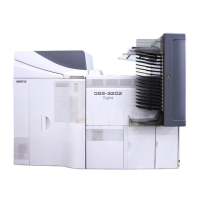
(2) Pass the optical fiber cables through square hole 2.
Fix the optical fiber cables with the clamps not to make them loose.
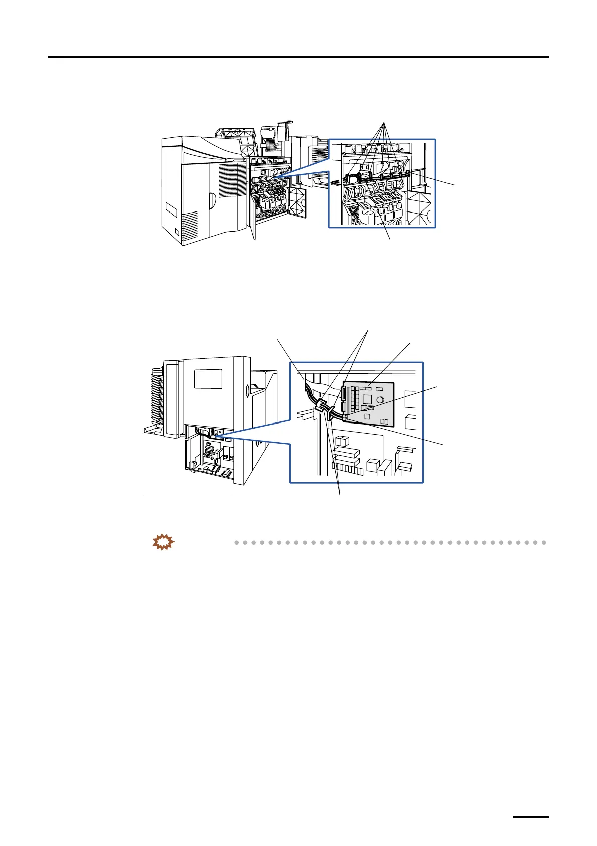
(3) Connect the optical fiber cables to the processor control PCB.
Fix the optical fiber cables with two clamps.
• For details about how to handle the optical fiber cable, refer to
☞Precautions for handling the optical
fiber cable and LVDS cable.
(4) Reattach the wiring cover and processor cover 1.
IMPORTANT
• Do not allow the cables to be pinched by the wiring duct cover.
(5) Reattach the wiring duct cover in the printer section.
Optical fiber cable
Clamps
Square hole 2
G068945
Square hole 2
Optical fiber cables
J/P518 (OUT)
Processor control PCB
J/P517 (IN)
Viewed from the right side
Clamps
G068970
Distributed by: minilablaser.com
 Loading...