5 Installing the machine and adjusting the level
68
*1. Only when the scanner is equipped.
This completes measuring the resistance.
5.5 Connecting the desk section and the printer section (signal cable)
IMPORTANT
• When you connect each cable, do not pull it by force and do not give extra pressure to the cable.
• Wire the cables with a wiring duct to prevent the cables from stepping on or getting caught.
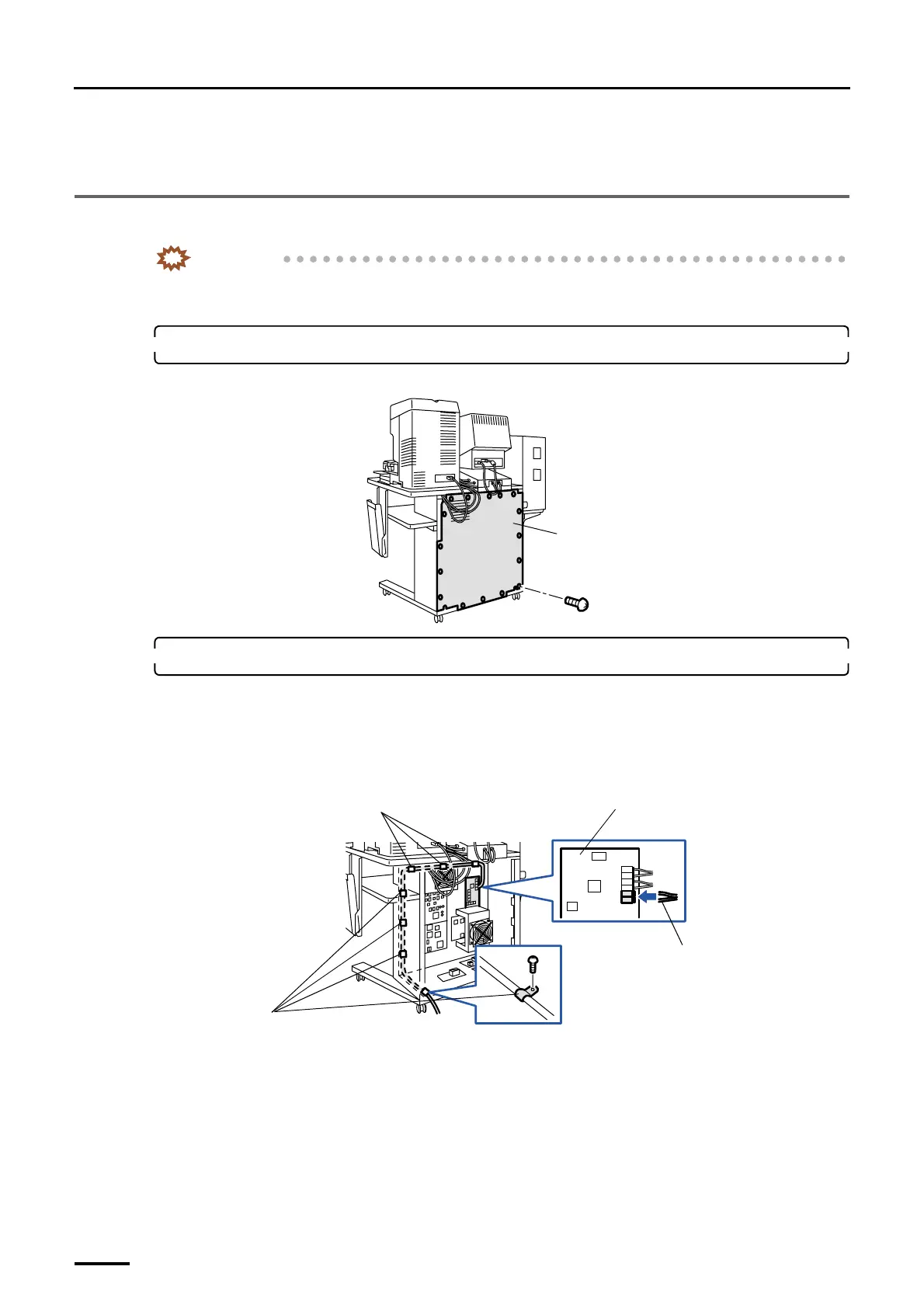
1. Remove the rear cover from the input section. (16 screws)
Example: For the machine with the scanner
2. Connect the cables from the printer section to the input section.
(1) Connect the optical fiber cables to the D-ICE control PCB.
Fix the optical fiber cables with seven clamps not to make them loose.
• For details about how to handle the optical fiber cable, refer to
☞Precautions for handling the optical
fiber cable and LVDS cable.
(2) Connect the connector of LVDS cable to the image processing PCB.
Fix the LVDS cable with two FG clamps and three clamps not to make them loose.
• For details about how to handle the LVDS cable, refer to ☞Precautions for handling the optical fiber
cable and LVDS cable.
Rear cover
G068952
D-ICE control PCB
Clamps
Optical fiber cable
Clamps
G070276
Distributed by: minilablaser.com


 To Next Page