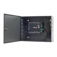
www.linearcorp.com 13 e3 eMerge Installation Instructions
5.2 Wiring the Inputs
All inputs may be con gured for normally open (factory default) or normally closed contacts with
supervision or non-supervision. Use standard 1k ohm resistors for supervision. Refer to Figure
5.1 for the acceptable wiring con gurations.
Figure 5.1. Input Circuit Confi gurations
Tamper Protection
A tamper switch is mounted inside the enclosure for connection to pin 5 and pin 6 on the
terminal strip. If the cover is removed for any reason the tamper switch will activate, triggering a
condition that can be linked to an event action in programming (e.g., send an e-mail or generate
an output).
Figure 5.2. Tamper Input Wiring
Note: Wiring methods
shall be in accordance
with the National
Electrical Code/NPFA 70
and all local codes.
Normally Open
Normally Closed
Normally Open
Normally Closed
SUPERVISED UNSUPERVISED
Resistor Value = 1k Ohm
Factory
Installed
Tam pe r
12VDC
TMP -
TMP +
FLT -
FLT +
–
+
Minimum Cable
Specifi cations: 22 AWG
Belden or equivalent.
Maximum distance: 2000
feet.
 Loading...