www.linearcorp.com 10 e3 eMerge Installation Instructions
4.2 Power Connection for Systems using the Metal
Enclosure
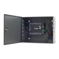
Systems using metal enclosures include a factory installed power supervision module as shown in
Figure 4.3.
Power Supply Connection
1. Connect 12VDC from the included power supply to the RED (+) and BLACK (-) leads
on the panel. Note: e3 eMerge systems require a 12VDC, 2 amp Class 2 power supply. Incorrect
voltage will damage the product and void the warranty.
2. Connect an earth ground to the green earth ground lead provided in the enclosure.
3. Turn on the power supply. If using a PIP for the power supply, it must be plugged into a
dedicated receptacle that is not controlled by a switch.
4. e power LEDs (DL17 and DL9) on the panel will turn on to indicate power is present.
5. Connect the leads to the battery (see below).
Figure 4.3. Power Connection for Systems using Metal Enclosure
Battery Connection
e metal enclosure provides charging and space for up to two 12VDC/7Ah sealed lead-acid
batteries (not included). e battery provides standby power when the primary power source is
lost. e control panel will utilize backup battery until the battery voltage reaches 11VDC at
which point the entire system shuts down.
Connecting Batteries in Parallel
Connecting batteries in parallel will double the capacity (amp hours) of the backup while
maintaining the proper voltage. Parallel connected battery connection is shown in Figure 4.3.
Warnings:
♦ Use caution when installing batteries. Incorrect use can damage the battery, controller or can
cause a re.
♦ Connect a maximum of two identical batteries in parallel. DO NOT connect batteries in
series. is will damage your system and void the warranty.
♦ e battery backup and charging uses advanced circuitry. Maximum charge rate is 650mA.
Once the battery is fully charged it is maintained with an occasional 10mA charge. Ensure
these ratings do not exceed the manufacturer’s rating for the battery.
♦ Properly dispose of old batteries.
RED RED
BLACKBLACK
BATTERY #1 BATTERY #2
Use minimum of 12GA stranded wire.
Use insulated terminals on battery terminals.
To Power Supervisor &
Battery Charger Module
Connect Batteries in Parallel !!!
DUAL BATTERY INSTALLATION
Note: Wiring methods
shall be in accordance
with the National
Electrical Code/NPFA 70
and all local codes.
Caution: A 12VDC power
supply MUST be used.
Incorrect voltage will
damage the product and
void the warranty.
Minimum
Cable Specifi cations
for power: 16 AWG
Belden (2 conductor) or
equivalent. Maximum
distance: 6 feet (1.8
meters).
Note: The system will
not power up using the
backup battery. The
12VDC power must be
present to power up the
system.
Note: Replace the
backup battery every 2 to
3 years.
Note: Parallel connected
batteries will take
approximately twice as
long to charge as a single
battery.
TMP -
TMP +
FLT -
FLT +
-
+
12VDC
Earth
Ground
Lead
- +
-
+
 Loading...