1-48
Installation 15088:J 10/22/99
WARNING:
Use extreme caution when working with the APS-6R - high voltage
and AC line-connected circuits are present in the APS-6R. Turn off
and remove all power sources. To reduce the risk of electric shock
make sure to properly ground the APS-6R.
Field Wiring an APS-6R
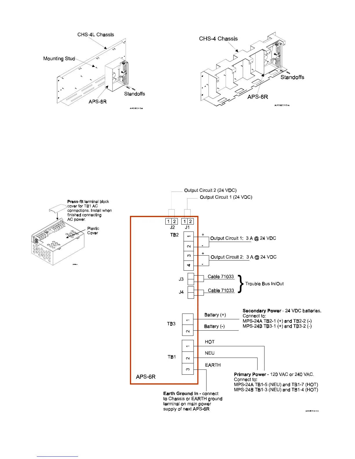
Figure 3.6-3 shows typical field wiring for an APS-6R
Figure 3.6-1 Mounting the APS-6R to a Chassis
3.6-1a 3.6-1b
Figure 3.6-2
Cover Installations
Before field wiring, install
the APS-6R plastic cover,
and install the press-fit
terminal block cover over
TB1 when field wiring is
complete (Figure 3.6-2).
Figure 3.6-3 Typical APS-6R Wiring
J1 and J2 may be used in place of TB2 when
the APS-6R is powering internal modules
(such as the UZC-256, XPC-8) with
compatible connectors
www.PDF-Zoo.com