1-66
Installation 15088:J 10/22/99
+ +
+ +
+ +
+ +
--
--
--
--
+ -
NOTES
• For additional ratings, refer to Appendix A.
• For connection of the initiating devices, refer to the manufacturer's installation instructions packaged with each device.
• For more information, refer to the MMX-2 Installation Instructions.
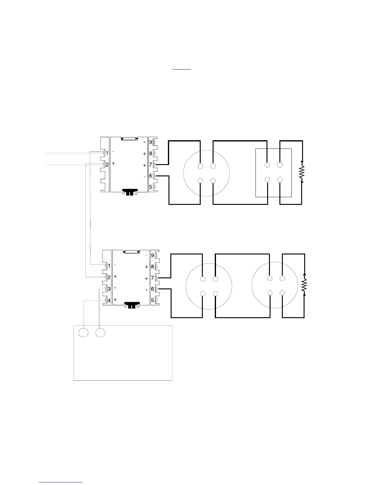
Figure 4.6-3 illustrates an MMX-1 monitoring normally open contact fire alarm initiating devices that do not
require power and an MMX-2 monitoring powered two-wire smoke detectors and a normally open contact alarm
initiating device. Refer to Figure 4.6-5 for circuits using four-wire detectors.
LIB SLC Port A ( - )
LIB SLC Port A (+)
MMX-1
MMX-2
Heat Detector Pull Station
24 VDC Two-wire Smoke Detectors
47K
End-of-Line
Resistor
(A2143-00)
A-2143-10
3.9K
Listed
End-of-
Line
Resistor
SLC Loop Channel A
Supervised and power-limited
Figure 4.6-3 NFPA Style B Initiating Device Circuit
Power-limited
UL-listed 24 VDC Filtered Regulated Power
Limited Power Supply for Fire Protective
Signaling
or
MPS-24A/E, TB3 Terminal 1 (+) and 2 (-)
APS-6R, TB2 Terminal 1 (+) and 2 (-)
Terminal 3 (+) and 4 (-)
www.PDF-Zoo.com