NFS2-3030/E Installation Manual — P/N 52544:N1 07/18/2014 21
Mounting a Cabinet Installation
Follow the instructions below.
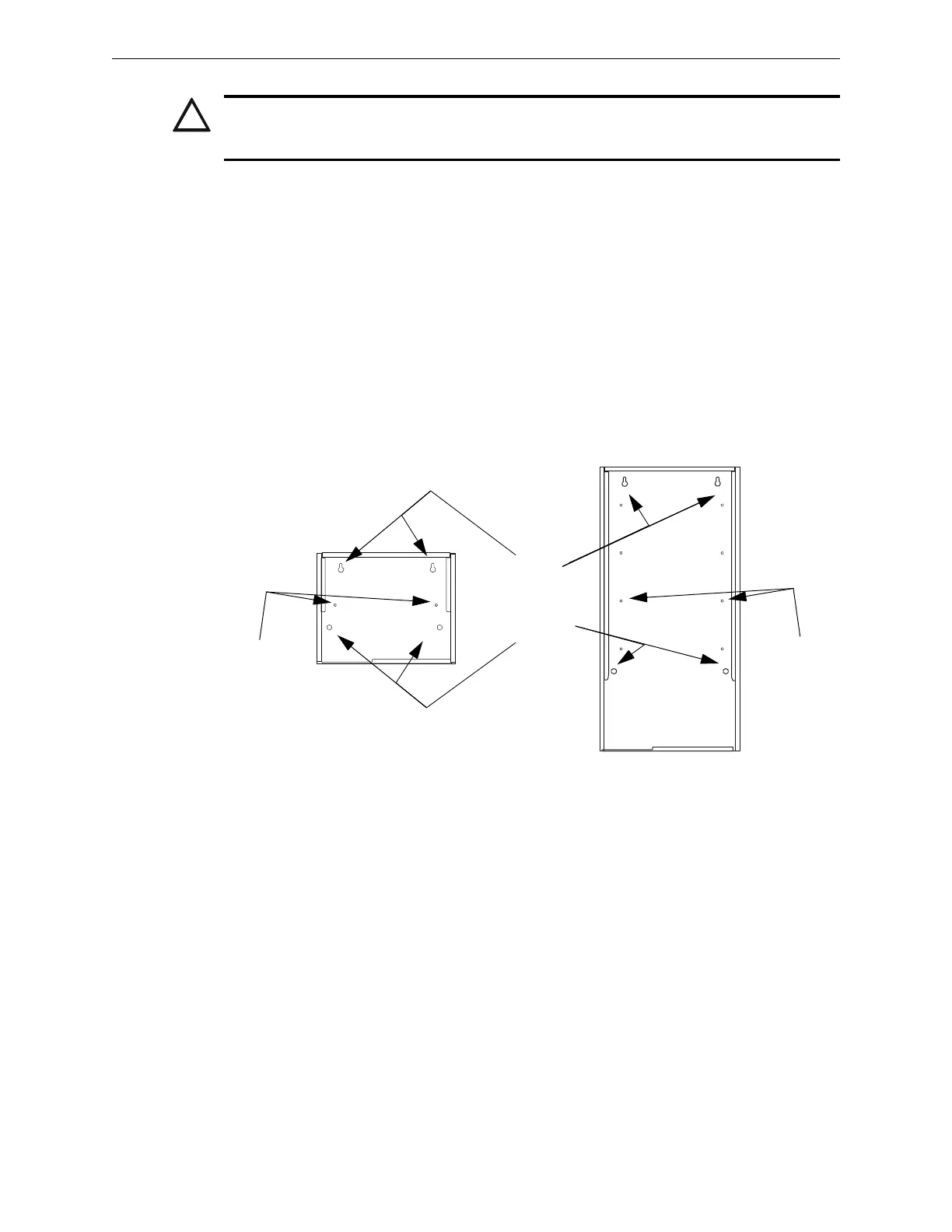
1. Mark and pre-drill holes for the top two keyhole mounting bolts.
2. Select and punch open the appropriate knock-outs. (For selection guidelines, see Section 3.11
“UL Power-limited Wiring Requirements”.)
3. Using the keyholes, mount the backbox over the two screws.
4. Mark the location for the two lower holes, remove the backbox and drill the mounting holes.
5. Mount the backbox over the top two screws, then install the remaining fasteners. Tighten all
fasteners securely.
6. Feed wires through appropriate knockouts.
7. Install CPU and other components according to this section, before installing hinges and door
(see CAB-3/CAB-4 Series Cabinet Installation Document).
CAUTION:
UNLESS YOU ARE FAMILIAR WITH THE PLACEMENT OF COMPONENTS WITHIN THIS
BACKBOX, ONLY USE THE KNOCKOUT LOCATIONS PROVIDED FOR CONDUIT ENTRY.
Keyholes
2 places
Mounting holes
2 places
CAB-4 Series backbox,
A-size (one-row)
CAB4cabinetmountingholes.cdr
CAB-4 Series backbox,
D-size (four-row)
Chassis-
mounting
studs
(2 per row of
backbox)
Chassis-
mounting
studs
(2 per row of
backbox)
Figure 3.1 Backbox-Mounting Holes and Chassis-Mounting Studs