NFS2-3030/E Installation Manual — P/N 52544:N1 07/18/2014 33
Form-C Relays on the CPU Installation
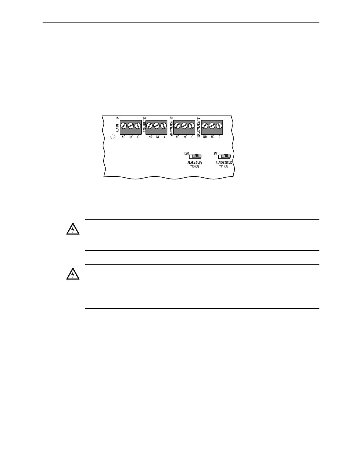
3.9 Form-C Relays on the CPU
The panel provides a set of Form-C relays. These are rated for 2 A at 30 VDC (resistive):
• Alarm - TB4
• Trouble - TB3
• Supervisory - TB2
• Security - TB1
The Supervisory and Security contacts can also be configured as Alarm contacts by setting
switches SW1 and SW2 away from the factory default positions shown in Figure 3.17.
3.10 Connecting Power Sources and Outputs
3.10.1 Overview
Complete all mounting procedures and check all wiring before applying power. Electrical
connections include the following:
• Primary power source. +24VDC, delivered through AMPS-24/AMPS-24E main power
supply. If AMPS-24/E is mounted in a separate cabinet, power-supply wiring must be in
conduit (for cabinet placement information see Section 3.4 “Laying Out Equipment in Cabinet
and Chassis” and the AMPS-24/E Manual.
• Secondary power source. +24 VDC from batteries, installed in the control panel (or in an
optional battery cabinet). Secondary (battery) power is required to support the system during
loss of primary power.
• External power sources. +24VDC auxiliary power supplies that are UL/ULC-listed for fire
protective service.
WARNING:
REMOVE ALL POWER SOURCES TO EQUIPMENT WHILE CONNECTING ELECTRICAL
COMPONENTS. LEAVE THE EXTERNAL, MAIN POWER BREAKER OFF UNTIL INSTALLATION
OF THE ENTIRE SYSTEM IS COMPLETE.
WARNING:
SEVERAL SOURCES OF POWER CAN BE CONNECTED TO THE CONTROL PANEL. BEFORE
SERVICING THE CONTROL PANEL, DISCONNECT ALL SOURCES OF INPUT POWER
INCLUDING THE BATTERY. WHILE ENERGIZED, THE CONTROL PANEL AND ASSOCIATED
EQUIPMENT CAN BE DAMAGED BY REMOVING AND/OR INSERTING CARDS, MODULES, OR
INTERCONNECTING CABLES.
SW1 set to Security
SW2 set to Supervisory
Move switch to opposite
position to convert to
Alarm relays.
3030-2-relays.wmf
Figure 3.17 Form-C Relay Connections