the circuit board. See Section 3 “Installation” for more details.
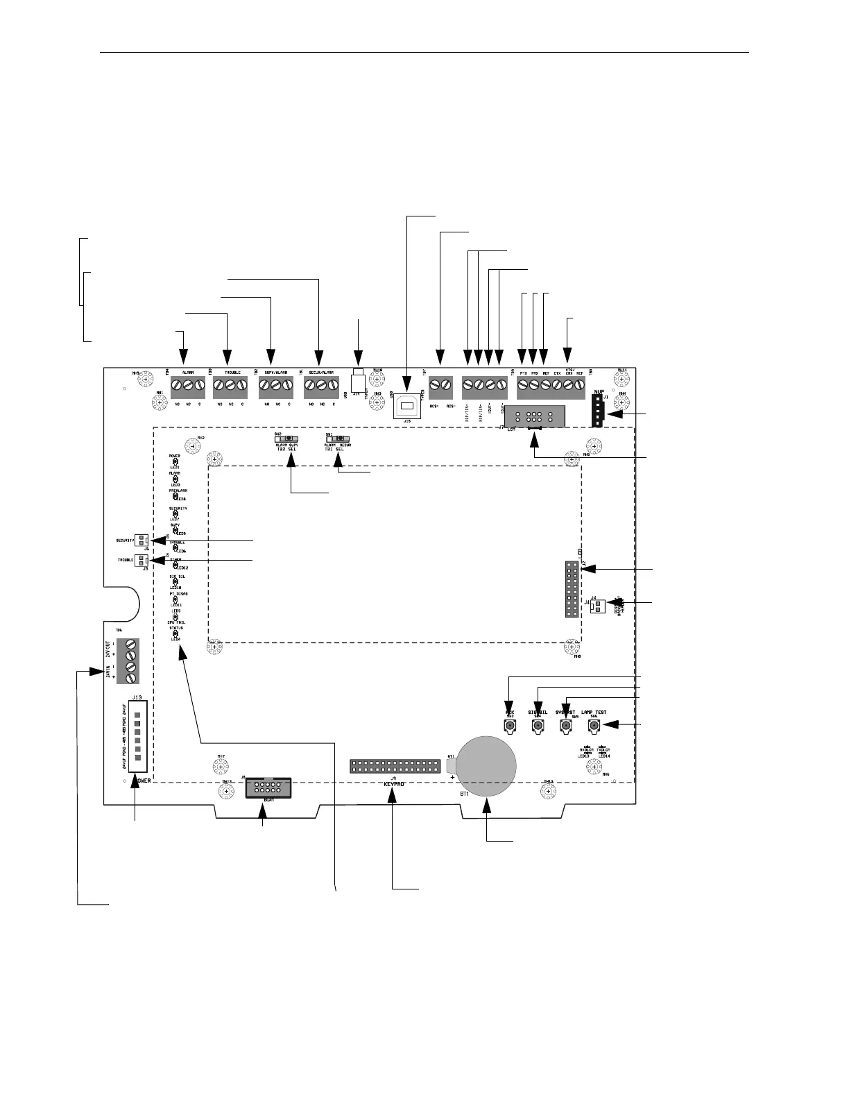
TB4 Alarm Relay
TB3 Trouble Relay
TB2 SUPV/ALARM Relay
TB1 SECUR/ALARM Relay
Note: Relay circuits are power-limited only if
connected to a power-limited signal source. Relays
are rated for 2A@30VDC resistive. See Figure 3.17,
“Form-C Relay Connections” on page 33.
SW2 Supervisory
SW1 Security
Future Use
TB7 ACS (power-limited, supervised)
TB9, RDP pins: LCD-160 or LCD-80 (supervised return)
*TB5, left side. Printer (isolated)
*TB5 CTX/CRX
CRT-2 or Keltron printer supervision
(TB5 CTX, REF No connection)
*J1, Network
Connection
(NUP), Cable
P/N 75556
J4 Backlight
connection
SW3 Acknowledge
SW4 Signal Silence
SW5 System Reset
SW6 Lamp Test
Lithium battery for backup of on-board
memory (See Section 3.5.4
“Memory-Backup Battery”)
J9 Keypad Connection
Test Fixture:
No connection
TB6 Accessory Power
(See Section 3.10 “Connecting
Power Sources and Outputs”)
J13 Power connections
(non-power-limited). See
Section 3.10 “Connecting
Power Sources and
Outputs”.
J6 Security switch connection
J5 Trouble bus connection
CPU23030.wmf
Status Indicator LEDs
(See Figure 2.3)
*J7 SLC Loop
Control and
Expander Modules
(LCM-320, LEM-320)
Cable P/N 75565
Service-level switches
for local operation
without keypad/display
Note: Dotted line indicates location of optional keypad & LCD display
*Circuits marked with an asterisk are supervised by communication loss.
See Appendix A, “Electrical Specifications” for details.
J2 LCD
Connection
TB9, TOut pins: LCD-80
J15 USB VeriFire Tools Connection