NFS2-3030/E Installation Manual — P/N 52544:N1 07/18/2014 49
Fire/Security Applications Applications
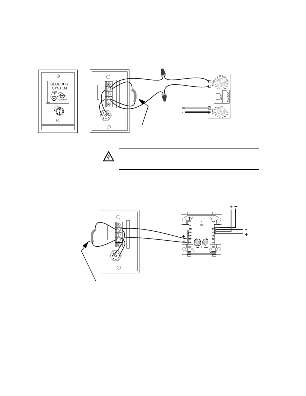
4.5.7 Connecting an RKS-S Remote Key Switch
The RKS-S Remote Key Switch arms and disarms the system. It can be mounted in a UL listed
single-gang electrical box. Both the monitor module and RKS-S must be mounted within the
protected area. Figure 4.7 and Figure 4.8, respectively, depict the connection of the FMM-101 or
FMM-1 module to the RKS-S.
Figure 4.7 Connecting the FMM-101 Module to the RKS-S
WARNING:
XP TRANSPONDER CIRCUITS (XPP-1, XPM-8, XPC-8, XPR-8,
XPM-8L) ARE NOT SUITABLE FOR SECURITY APPLICATIONS.
FMM-101
yellow (–)
purple (+)
SLC
red (+)
black (–)
R-47K
End-of-Line
Resistor
RKS-S (rear)
RKSFMM101.wmf
RKS-S rear
FMM-1
RKSFMM-btpH.wmf
SLC Out
SLC
In
R-47K
End-of-Line
Resistor
Figure 4.8 Connecting the FMM-1 Module to the RKS-S
*If the SLC device does
not match the one in this
figure, refer to the SLC
manual appendix, which
contains wiring conversion
charts for type V and type
H modules.