24 NFS2-3030/E Installation Manual — P/N 52544:N1 07/18/2014
Installation Attaching the CPU & Chassis
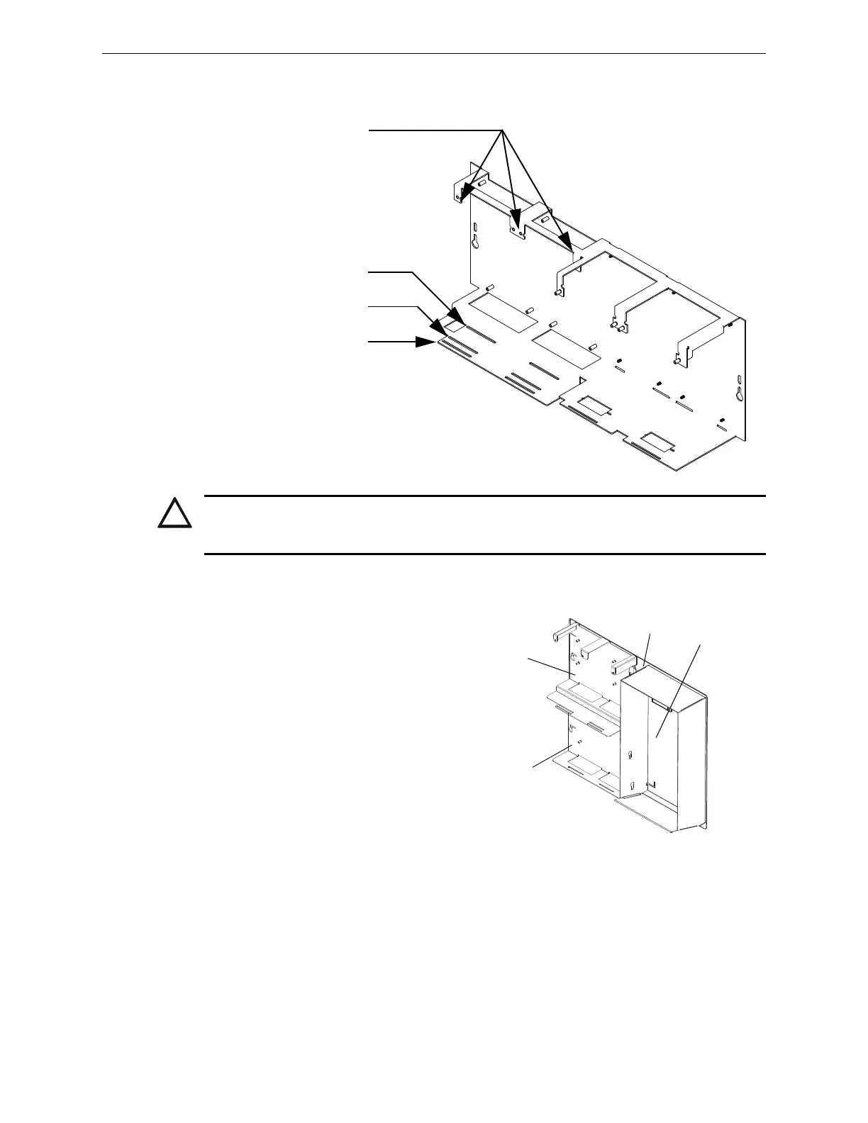
3. Place the board over the stand-offs so that mounting holes line up with those on the chassis.
Secure all stand-offs with screws provided.
3.5.2 Mounting in the CA-2 Audio System Chassis
The NFS2-3030 will mount into the CA-2
chassis assembly—along with a DVC,
microphone and optional telephone handset—
as part of an audio command center
installation.
The CA-2 is a two-row assembly consisting of
• a back plate that attaches to the backbox
• two half-chassis, each of which takes up
the left half of a backbox row
• a microphone and telephone handset well
• a microphone
CA-2 can also mount TELH-1, an optional
telephone handset.
CAUTION:
IT IS CRITICAL THAT ALL MOUNTING HOLES OF THE FIRE ALARM CONTROL PANEL ARE
SECURED WITH A SCREW OR STAND-OFF TO INSURE CONTINUITY OF EARTH GROUND.
CPU standoffs at Positions 1 and 2:
1.5 inch (38.1 mm) for use with CPU2-3030D
or 0.25 inch (6.35 mm) for use with CPU2-3030ND
CHS-M3.cdr
CPU2-3030ND
(without keypad/display)
CPU2-3030D
(with keypad/display)
Chassis-mounting slots
Figure 3.5 Standoffs on Chassis CHS-M3
Do Not Use.
Figure 3.6 CA-2 Chassis Assembly
CA2chassisassembly.wmf
Upper
half-chassis
(FACP)
Lower
half-chassis
(DVC)
Microphone
and
handset
well
Back plate